Sck ss mosi miso – Freescale Semiconductor MPC5200B User Manual
Page 571
MPC5200B Users Guide, Rev. 1
15-60
Freescale Semiconductor
PSC Operation Modes
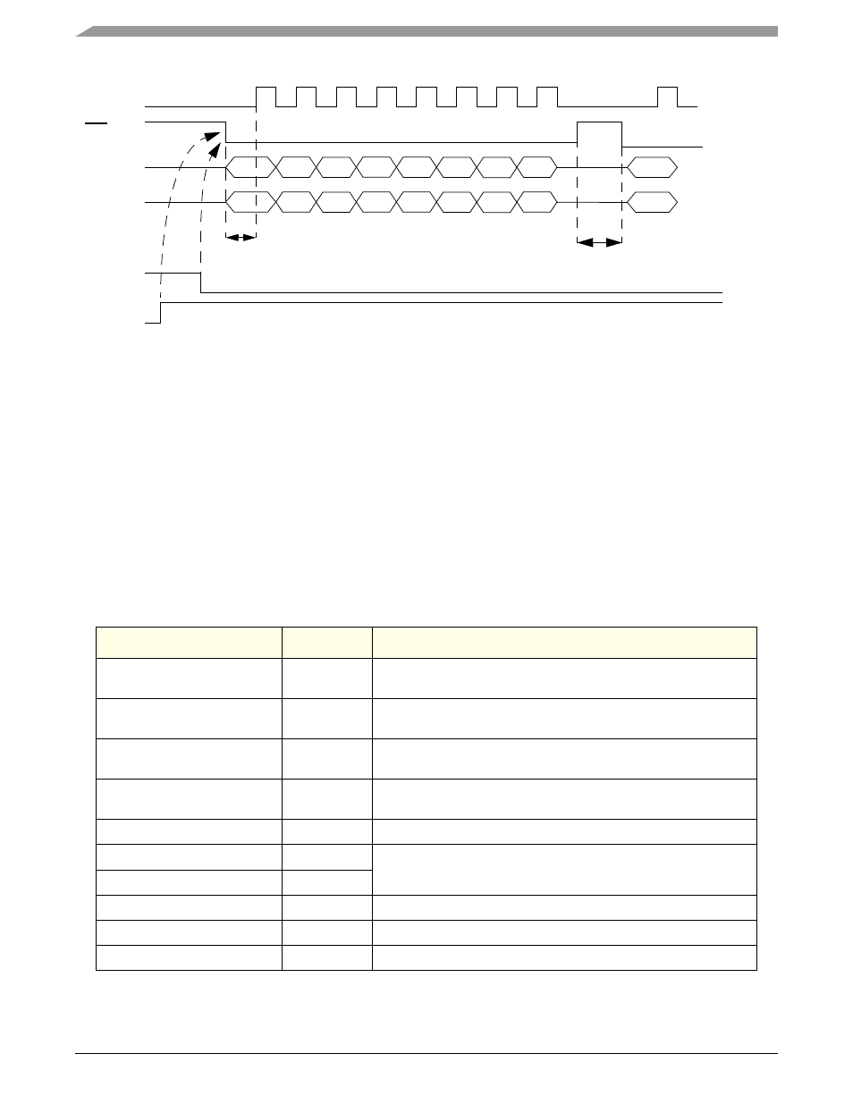
Figure 15-13. SPI Parameter
shows an example how to configure the PSC3 as SPI master.
•
32bit data
•
clock is active high, CPOL = 1;
•
the first SCK edge is issued one half cycle into the data transfer; CPHA = 0
•
msb first
•
Baud Rate 1MBit
•
DSCLK delay = 0.5
µs
•
DTL delay = 2.0
µs
•
set the
TFALARM
level to 0x010, alarm occurs if 16 byte are in the TxFIFO
•
set the
level to 0x00C, alarm occurs if 12 byte space in the RxFIFO
•
enable TxRDY interrupt
Table 15-85. 32-bit SPI Master mode for PSC3
Register
Value
Setting
0x0A
Disable the Tx and Rx part for configuration if the PSC was enabled
by the work before.
0x0F00E000
Select the 32bit Codec SPI master mode, msb first, CPOL = 1,CPHA
= 0
cdm_psc345_bitclk_config
0x8020
divide the
f
system
clock frequency from 528 to 16 MHz Mclk, see
Section 5.5.13, PSC3 Mclock Config Register—MBAR + 0x0230
cdm_clock_enable_register
0x00000080
enable Mclk, see
Section 5.5.6, CDM Clock Enable Register—MBAR +
0x070F
set the SCK and DSCKL delay
0x00
set the DTL delay 2us
0x84
0x000C
set the RFALARM level to 0x00C
TFALARM
0x0010
set the TFALARM level to 0x010
0x0100
enable TxRDY interrupt
SCK
SS
MOSI
MISO
DTL
DSCKL
NEXT
FRAME
TX FIFO
TX
ENABLE
EMPTY
The PSC starts to generate the SCK if the transmitter is enabled and the
Tx FIFO is not empty!