2 i2c controller, 1 start signal, 2 stop signal – Freescale Semiconductor MPC5200B User Manual
Page 619: Section 18.2, i, C controller, Figure 18-1
MPC5200B Users Guide, Rev. 1
18-2
Freescale Semiconductor
I
2
C Controller
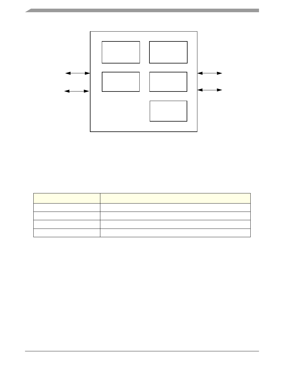
Figure 18-1. Block Diagram—I
2
C Module
18.2
I
2
C Controller
The I
2
C has simple bidirectional two-wire bus for efficient inter-IC control. The two wires, serial data line (SDA) and serial clock line (SCL),
carry information between MPC5200B and other devices connected to the bus. Each device, including MPC5200B, is recognized by a unique
address, and can operate as either transmitter or receiver, depending on the function of the device. In addition to the transmitters and receivers,
devices can be considered as masters or slaves. A master is the device which initiates a data transfer on the bus and generates the clock signals
to permit that transfer. At that time, any device addressed is considered a slave. See
.
Standard communication usually has 4 functional areas:
•
START signal
•
slave address transmission
•
data transfer
•
STOP signal
Activities listed above are briefly described in the sections below. Also see
18.2.1
START Signal
A START signal is defined as a high-to-low transition of SDA while SCL is high. This signal denotes the beginning of a new data transfer
and wakes up all slaves. Each data transfer may contain several data bytes.
When the bus is free, (i.e., no master device is engaging the bus) both SCL and SDA lines are at a logical high. A master initiates
communication by sending a START signal.
18.2.2
STOP Signal
A STOP signal is defined as a low-to-high transition of SDA while SCL is high.
Table 18-1. I
2
C Terminology
Term
Description
Transmitter
Device that sends data to bus.
Receiver
Device that receives data from bus.
Master
Device that initiates transfer, generates SCL, and terminates transfer.
Slave
Device that is addressed by master.
IP Bus
Address
Compare
Data Shift
Register
In/Out
Start, Stop
& Arbitration
Control
Control
Clock
Registers
SCL
SDA
CommBus