1 protocol architecture, Protocol architecture -29, Bdlc protocol handler outline -29 – Freescale Semiconductor MPC5200B User Manual
Page 708: Section, 1, protocol architecture
Functional Description
MPC5200B Users Guide, Rev. 1
Freescale Semiconductor
20-29
20.8.3.1
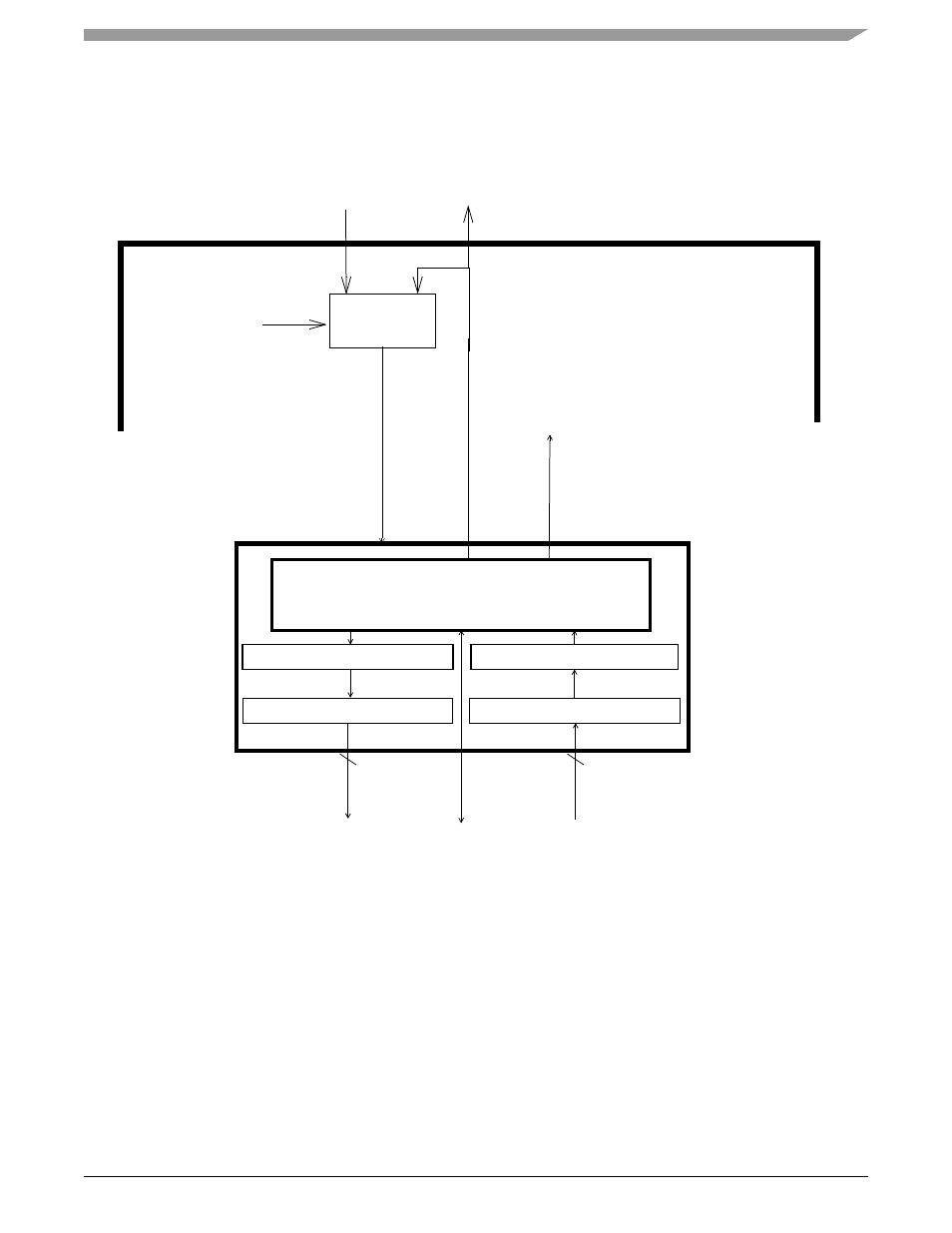
Protocol Architecture
The Protocol Handler contains the State Machine, Rx Shadow Register, Tx Shadow Register, Rx Shift Register, Tx Shift Register, and
Loopback Multiplexer as shown in
. Each block will now be described in more detail.
Figure 20-12. BDLC Protocol Handler Outline
•
Rx & Tx Shift Registers
The Rx Shift Register gathers received serial data bits from the J1850 bus and makes them available in parallel form to the Rx
Shadow Register. The Tx Shift Register takes data, in parallel form, from the Tx Shadow Register and presents it serially to the State
Machine so that it can be transmitted onto the J1850 bus.
•
Rx & Tx Shadow Registers
Immediately after the Rx Shift Register has completed shifting in a byte of data, this data is transferred to the Rx Shadow Register
and RDRF or RXIFR is set and interrupt is generated if the interrupt enable bit (IE) in BDLC Control Register 1 is set. After the
transfer takes place, this new data byte in the Rx Shadow Register is available to the CPU, and the Rx Shift Register is ready to shift
in the next byte of data. Data in Rx Shadow Register must be retrieved by the CPU before it is overwritten by new data from the Rx
Shift Register.
Once the Tx Shift Register has completed its shifting operation for the current byte, the data byte in the Tx Shadow Register is
loaded into the Tx Shift Register. After this transfer takes place, the Tx Shadow Register is ready to accept new data from the CPU.
Rx Shift Register
To IP bus Interface & Rx/Tx Buffer’s
State Machine
To Pad Drivers
Rx
Data
Tx
Da
ta
Control
8
Tx Shift Register
TXB
DI
GI
TA
L FI
LT
ER IN
Control
8
Rx Shadow Register
Tx Shadow Register
Loopback
RXB
loopback
control
TXB
Multiplexer
DLOOP from DLCBCR2
BDLC