Freescale Semiconductor MPC5200B User Manual
Page 308
Registers
MPC5200B Users Guide, Rev. 1
Freescale Semiconductor
10-11
10.3.1.5
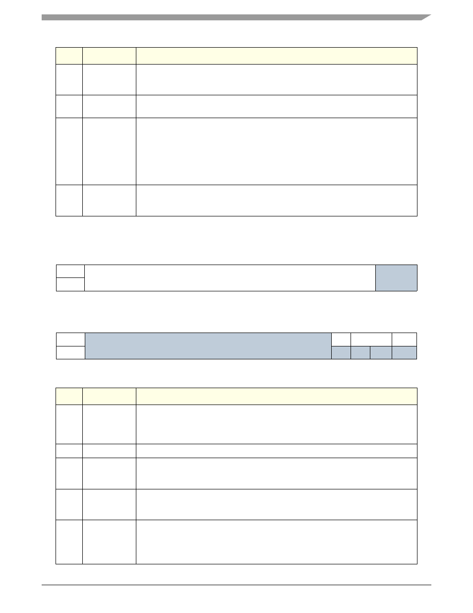
Base Address Register 0 PCIBAR0(RW) —MBAR + 0x0D10
Bits
Name
Description
0:7
Built-In Self
Test
(BIST)
Fixed to 0x00. The PCI controller does not implement the Built-In Self Test register.
Initialization software should write a 0x00 to this register location.
8:15
Header Type
Fixed to 0x00. The PCI controller implements a Type 0 PCI Configuration Space Header.
Initialization software should write a 0x00 to this register location.
16:23
Latency Timer
This register contains the latency timer value, in PCI clocks, used when MPC5200B is the
PCI master. The lower three bits of the register are hardwired low and the upper five bits are
programmable (read/write from both the IP bus and PCI bus Configuration cycles).
Note: The MPC5200B does NOT support initiator latency time-outs, the internal PCI Arbiter
does not support preemption of the internal masters XIPCI or SCPCI. The internal master
is granted until the transaction has been completed. The Latency Timer (LT) cannot
terminate any transfer.
28:31
Cache Line
Size
The four lower bits of this register are programmable (read/write from both the IP bus and
PCI bus Configuration cycles). The value programmed specifies the cacheline size in units
of DWORDs.
msb
0
1
2
3
4
5
6
7
8
9
10
11
12
13
14
15
R
Base Address 0
Reserved
W
RESET
0
0
0
0
0
0
0
0
0
0
0
0
0
0
0
0
16
17
18
19
20
21
22
23
24
25
26
27
28
29
30
31 lsb
R
Reserved
pref
range
IO/M#
W
RESET
0
0
0
0
0
0
0
0
0
0
0
0
0
0
0
0
Bits
Name
Description
0:13
Base Address
Register 0
(BAR0)
MPC5200B PCI Base Address Register 0 (256Kbyte). Applies only when MPC5200B is
target. These bits are programmable (read/write from both the IP bus and PCI bus
Configuration cycles). This BAR register should be used to point at the internal MPC5200B
register space (MBAR)
14:27
Reserved
These bits are reserved.
28
prefetchable
access
(pref)
Fixed to 0. This bit indicates that the memory space defined by BAR0 is NOT prefetchable.
Configuration software should write a 0 to this bit location.
29:30
range
Fixed to 00. This register indicates that base address 0 is 32 bits wide and can be mapped
anywhere in 32-bit address space. Configuration software should write 00 to these bit
locations.
31
IO or Memory
Space
(IO/M#)
Fixed to 0. This bit indicates that BAR0 is for memory space. Configuration software should
write a 0 to this bit location.
0 = Memory
1 = I/O