2 transmitting and receiving in mir mode, Transmitting and receiving in mir mode -61, Psc mir and fir block diagram -61 – Freescale Semiconductor MPC5200B User Manual
Page 579: Figure 15-19, Figure, This zero was insert after five consecutive ones
MPC5200B Users Guide, Rev. 1
15-68
Freescale Semiconductor
PSC Operation Modes
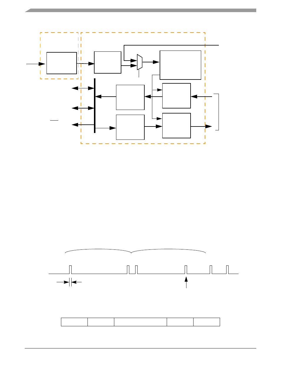
Figure 15-19. PSC MIR and FIR Block Diagram
For MIR and FIR mode the clock for the transmitter and receiver is generated by dividing down from the internal Mclk or from an external
clock. If the bit GenClk in the
was set to “1” then PSC generate the clock from the internal source. The clock from the Mclk generator
goes through a pre-divider to the clock generator. See
Section 15.2.26, Infrared MIR Divide Register (0x50)—IRMDR
or
Infrared FIR Divide Register (0x54)—IRFDR
for the possible frequencies for this mode. For more informations about the Mclk divider see
Section 5.5.11, PSC1 Mclock Config Register—MBAR + 0x0228
. If the bit GenClk cleared then the PSC use the clock from an external source
for the clock generation.
NOTE
If the
register was not changed (reset value 0x01) then the counter divide the clock (Mclk) by
2. This is the minimum value. 0x00 deactivate the clock generation.
15.3.4.2.2
Transmitting and Receiving in MIR Mode
Each bit data is encoded so that a 0 is encoded as 1/4 of the bit time pulse and a 1 is encoded as no pulse. Similarly, the received serial pulse
is decoded as a 0 and an absence of a pulse is decoded as a 1. The PSC MIR mode use the HDLC bit stuffing after five consecutive ones to
decode/encode the data, except the STA and STO flag. For example see the Figure below:
The packet format is:
STA
STA
DATA
FCS
STO
01111110
01111110
DATA
16 bit CRC
01111110
Receiver
Transmitter
Rx FIFO
Tx FIFO
Clock
Generation
Unit
IRDA_RX
IRDA_TX
External
Interface
Signals
IPB
Interface
CommBus
Interface
IRQ
Controller
BestComm
Request
PSC
IRMDR[1:7] for MIR mode
Mclk
Divider
CDM
Mclk
f
system
Clock
divider
IR_USB_CLK
BitClkDiv[0:7]+1
IRFDR[4:7] for FIR mode
IrdaClk
0
1
SICR[GenClk]
MclkDiv[8:0]+1
binary data
0
1/4 of the bit width
1
1
1
1
1
1
0
0
1
1
1
1
Flag
1
0
1
1
character FE
0
1
0
1
This zero was insert after five
consecutive ones!