1 fec rx fifo data register-mbar + 0x3184, 7 fec tx fifo data register-mbar + 0x31a4, 1 fec rx fifo status register-mbar + 0x3188 – Freescale Semiconductor MPC5200B User Manual
Page 493: 8 fec tx fifo status register-mbar + 0x31a8, Fec rx fifo data register—mbar + 0x3184 -28, Fec tx fifo data register—mbar + 0x31a4 -28, Fec rx fifo status register—mbar + 0x3188 -28, Fec tx fifo status register—mbar + 0x31a8 -28, Fec rx fifo status register -28, 0x318
MPC5200B Users Guide, Rev. 1
14-28
Freescale Semiconductor
FEC Tx FIFO Data Register—MBAR + 0x31A4
14.6.1
FEC Rx FIFO Data Register—MBAR + 0x3184
14.7
FEC Tx FIFO Data Register—MBAR + 0x31A4
The RFIFO_DATA and TFIFO_DATA registers are the main interface port for the transmit and receive FIFO. Data which is to be buffered in
the FIFO, or has been buffered in the FIFO, is accessed through this register.
14.7.1
FEC Rx FIFO Status Register—MBAR + 0x3188
14.8
FEC Tx FIFO Status Register—MBAR + 0x31A8
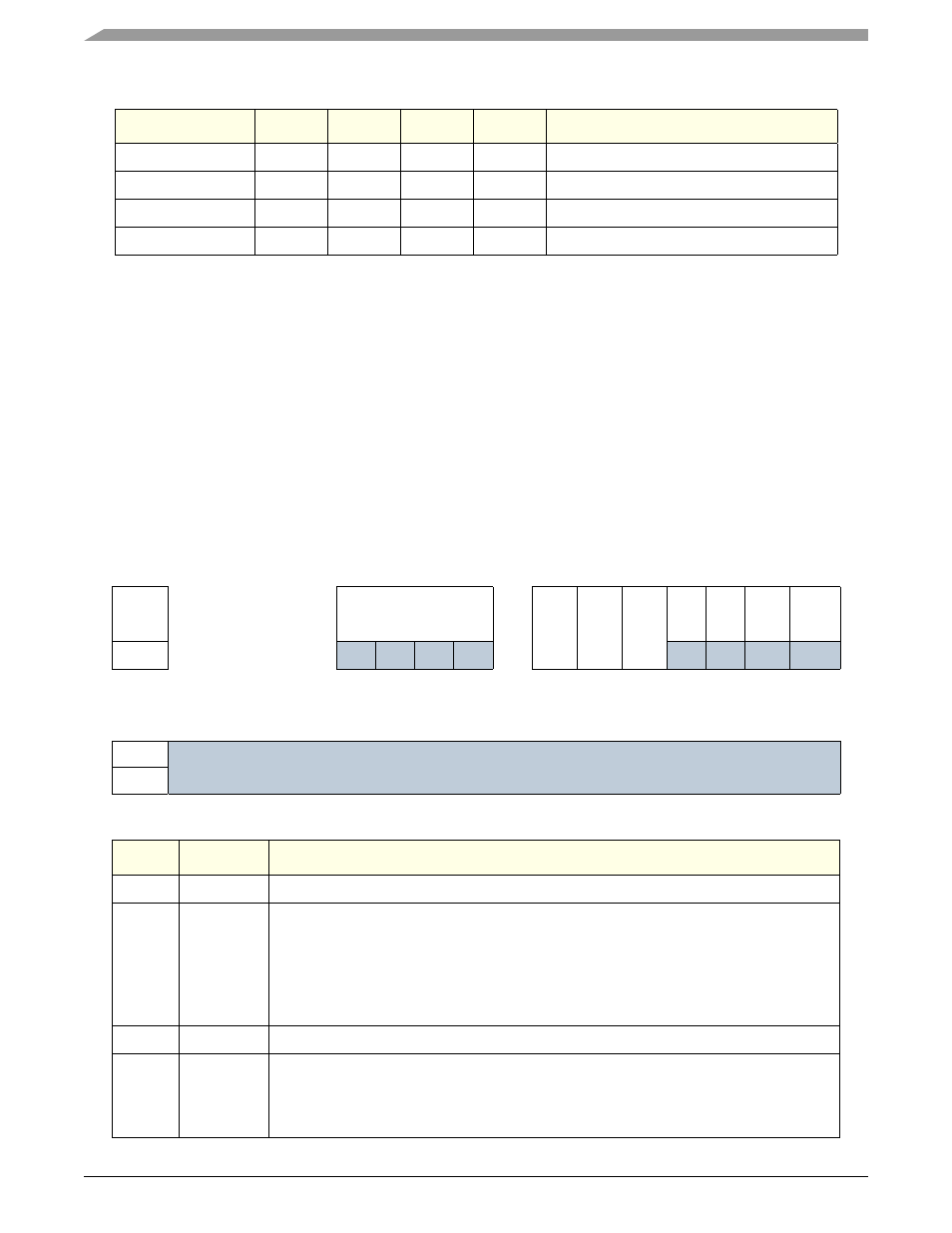
The RFIFO_STATUS and TFIFO_STATUS registers contain bits which provide information about the status of the FIFO controller. The bits
marked sticky are cleared by writing a “1” to their positions.
0x1B4
LWF
LWF
Transmit Last Write Frame Pointer
0x1B8
Alarm
Alarm
Transmit (High/Low) Alarm Pointer
0x1BC
Read
Read
Transmit FIFO Read Pointer
0x1C0
Write
Write
Transmit FIFO Write Pointer
Table 14-31. FEC Rx FIFO Status Register
FEC Tx FIFO Status Register
msb 0
1
2
3
4
5
6
7
8
9
10
11
12
13
14
15
R
IP
TXW
TYP
E
[1]
TYP
E
[0[
Frame[0:3]
FAE
RXW
UF
OF
FR
Full
Alarm
Empty
W
RESET:
0
0
0
0
0
0
0
0
0
0
0
0
0
0
1
1
16
17
18
19
20
21
22
23
24
25
26
27
28
29
30
31 lsb
R
Reserved
W
RESET:
0
0
0
0
0
0
0
0
0
0
0
0
0
0
1
1
Bits
Name
Description
0:3
—
Reserved
4:7
Frame[0:3]
Frame Indicator – READ ONLY
This bus provides a frame status indicator for non-DMA applications.
Frame[0] = A frame boundary has occurred on the [31:24] byte of the data bus.
Frame[1] = A frame boundary has occurred on the [23:16] byte of the data bus.
Frame[2] = A frame boundary has occurred on the [15:8] byte of the data bus.
Frame[3] = A frame boundary has occurred on the [7:0] byte of the data bus.
8
---
Reserved
9
Error
FIFO Error – Sticky, Write To Clear.
This bit signifies that an error has occurred in the FIFO controller. Errors can be caused by
underflow, overflow,or pointers being out of bounds. This bit will remain set until this bit of the
FIFO status register has been written with a 1.
Table 14-30. FIFO Interface Register Map (continued)
Address
byte0
byte1
byte2
byte3
Description