4 host control ( hc ) operational registers, 1 programming note, Host control (hc) operational registers -5 – Freescale Semiconductor MPC5200B User Manual
Page 408: Programming note -5, Sample interrupt endpoint schedule -5, Section 12.4, Includes, 4 host control (hc) operational registers
Host Control (HC) Operational Registers
MPC5200B Users Guide, Rev. 1
Freescale Semiconductor
12-5
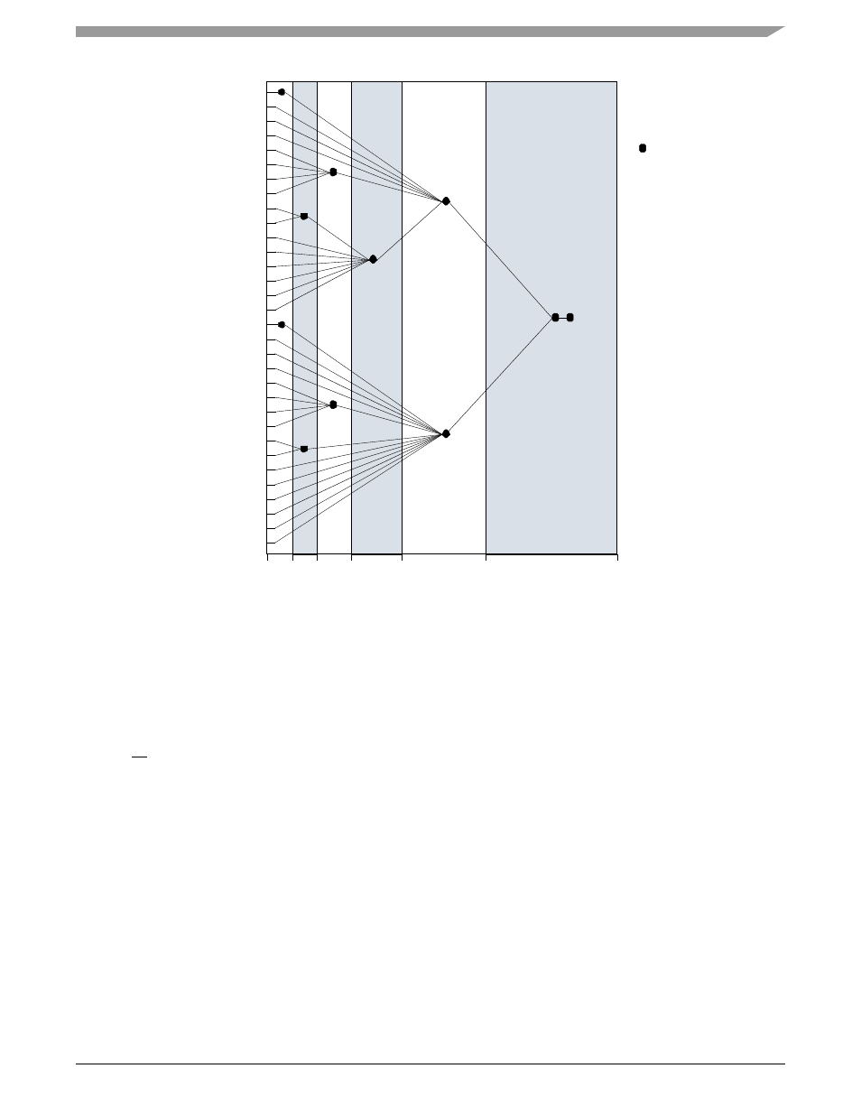
Figure 12-5. Sample Interrupt Endpoint Schedule
12.4
Host Control (HC) Operational Registers
Host Control contains a set of on-chip operational registers which are mapped into a non-cacheable portion of the system addressable space.
These registers are used by the HCD. According to the function of these registers, they are divided into four partitions, specifically for control
and status, memory pointer, frame counter and root hub. All of the registers should be read and written as 32-bit words.
Reserved bits may be allocated in future releases of this specification. To ensure interoperability, the HCD that does not use a reserved field
should not assume the reserved field contains 0. In addition, HCD should always preserve the reserved field value(s).
When a R/
W
register is modified, the HCD should first read the register and modify the bits desired. Then, HCD should write the register
with the reserved bits still containing the read value. Alternatively, HCD can maintain an in-memory copy of previously written values that
can be modified and written to the HC register. When a write to the set/clear register is written, bits written to reserved fields should be 0.
12.4.1
Programming Note
Programmers should observe the following notes:
1.
CDM 48MHz Fractional Divider Configuration Register—MBAR + 0x0210
must be initialized before you can access any USB
registers. If this register is not initialized, every USB register access will cause a machine check interrupt.
For Example: If the SYS_XTAL_IN frequency is 33 MHz and the RST_CFG6 pin is low (multiplier 16), than the four phase divide
ratios must be set to 0x5,fractional counter divide ration of f
system
/11. 33 MHz * 16 / 11 = 48 MHz (USB frequency)
2.
The
GPS Port Configuration Register—MBAR + 0x0B00
must be initialized to communicate over the muxed USB port. It
configures USB for Differential or SE0 mode, the port to be used for USB2 and if the IrDA/USB 48MHz clock is generated
internally or externally.
0
17
8
1
2
3
4
5
6
7
9
10
11
12
13
14
15
16
24
20
28
18
26
22
30
25
21
29
19
27
23
31
32 16
8
4
2
1
Endpoint Poll Interval (ms)
Interrupt
Endpoint
Descriptor
Interrupt
Headpointers