11 psc1 mclock config register-mbar + 0x0228, Psc1 mclock config register—mbar + 0x0228 – Freescale Semiconductor MPC5200B User Manual
Page 154
CDM Registers
MPC5200B Users Guide, Rev. 1
Freescale Semiconductor
5-21
5.5.11
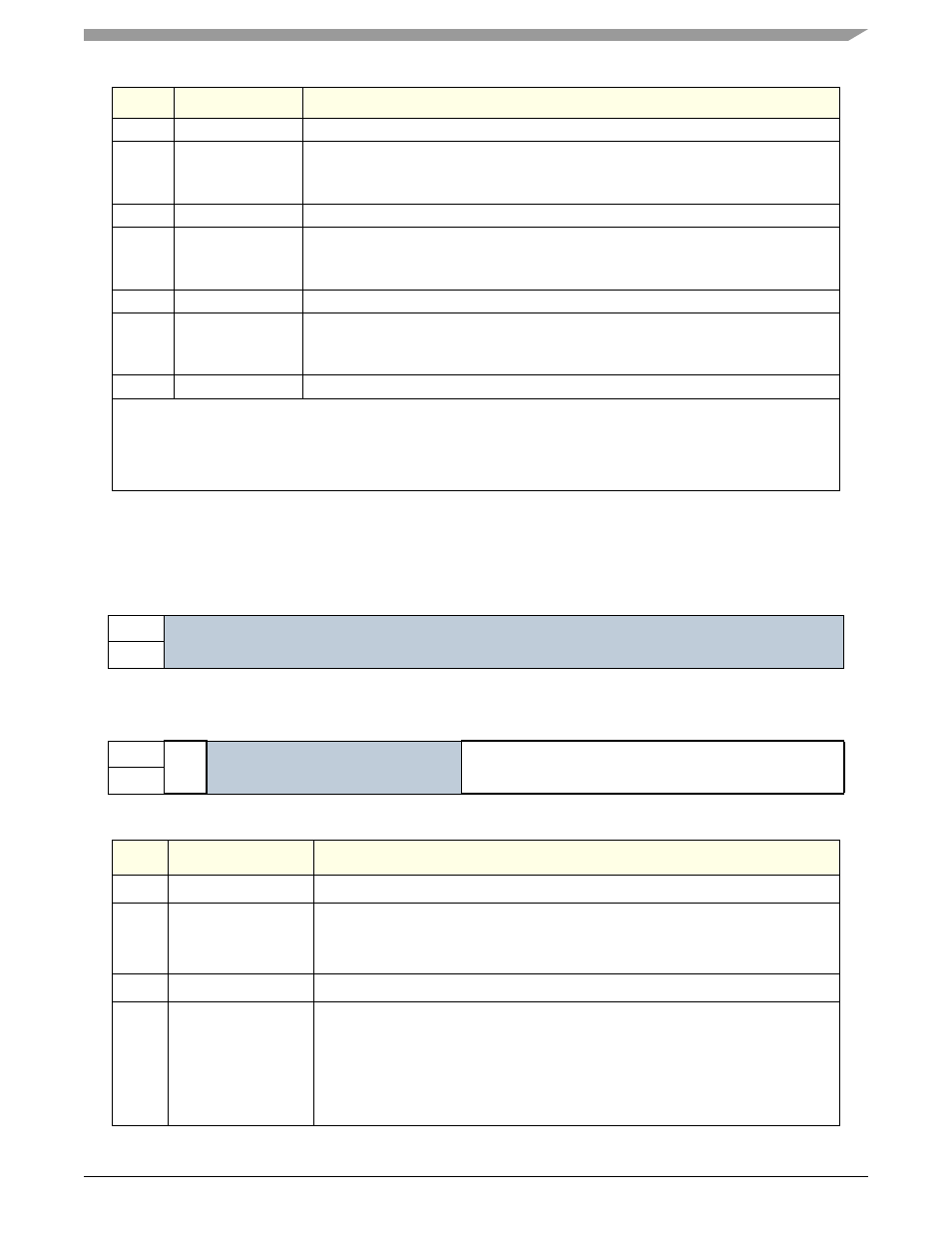
PSC1 Mclock Config Register—MBAR + 0x0228
This register controls the generation of the Mclk for PSC1. Before modify the register value the divider must be disabled.
Bit
Name
Description
0–6
—
Reserved for future use. Write 0.
7
pll_lock
1
CDM System PLL Lock Detect—read-only status bit.
bit=1:CDM has detected System PLL lock condition.
bit=0:CDM has NOT detected System PLL lock condition.
8–14
—
Reserved for future use. Write 0.
15
pll_lost_lock
CDM System PLL Lock Lost—hardware can only set this bit, register write must clear bit.
bit=1:CDM detected loss of PLL lock after PLL lock has been achieved.
bit=0:CDM has not detected loss of PLL lock (state before PLL lock occurs).
16–22
—
Reserved for future use. Write 0.
23
pll_small_
lock_window
PLL Small Lock Window—pulse width used to detect rising edge of PLL FREF clock.
bit=1:lock window pulse width 2
f
VCOsys
clock periods.
bit=0:lock window pulse width 4
f
VCOsys
clock periods.
24–31
—
Reserved for future use. Write 0.
Note:
1.
System PLL Lock Condition—256 System PLL FREF clock rising edges within PLL_Lock_Window (System PLL FFB
rising edge). In PLL bypass mode, Lock is active after 256 System Oscillator clock rising edges.
2.
In current MPC5200B CDM the PLL Lock Circuitry is for information only. CDM does not wait for PLL lock to start clocks
or use PLL_LOST_LOCK as an interrupt source.
Table 5-18. CDM PSC1 Mclock Config
msb 0
1
2
3
4
5
6
7
8
9
10
11
12
13
14
15
R
Reserved
Write 0
W
RESET:
0
0
0
0
0
0
0
—
0
0
0
0
0
0
0
—
16
17
18
19
20
21
22
23
24
25
26
27
28
29
30
31 lsb
R
Mc
loc
k
Enab
le
Reserved
Write 0
MclkDiv[8:0]
W
RESET:
1
0
0
0
0
0
0
0
0
0
0
0
1
1
1
1
Bit
Name
Description
0–15
—
Reserved for future use. Write 0.
16
Mclock Enable
PSC1 Mclock enable.
bit=0:Turns off internally generated Mclock.
bit=1:Turns on internally generated Mclock.
17-22
—
Reserved for future use. Write 0.
23-31
MclkDiv[8:0]
The counter divide the f
system
frequency by MclkDiv+1. A vallue of 0x00 in this
register turns off internally generated Mclock.
For example, a value of 7 in this register, where fsystem clock is at a frequency of
528MHz would result in a Mclock rate of 528/8, or 66 MHz.
Note:
f
system
clock is always 12 or 16 times the reference clock, sys_xtal_in,
depending on sys_pll_cfg_0 at reset.