3 ata drive registers-mbar + 0x3a00, 1 ata drive device control register-mbar + 0x3a5c, Section 11.3.3 – Freescale Semiconductor MPC5200B User Manual
Page 377: Section 11.3.3, ata drive registers—mbar + 0x3a00, 1 ata drive device control register—mbar + 0x3a5c
MPC5200B Users Guide, Rev. 1
11-12
Freescale Semiconductor
ATA Register Interface
11.3.3
ATA Drive Registers—MBAR + 0x3A00
The ATA drive registers are physically located inside the drive controller on the ATA disk drive. The MPC5200B ATA Host Controller
provides access to these registers using the chip selects and address bits.
ATA Drive is controlled by 32-bit registers. These registers are located at an offset from MBAR of 0x3a00. Register addresses are relative to
this offset. Therefore, the actual register address is:
MBAR + 0x3A00 + register address
Hyperlinks to the ATA Drive registers are provided below:
11.3.3.1
ATA Drive Device Control Register—MBAR + 0x3A5C
Bits
Name
Description
0:19
—
Reserved
20:31
WritePtr
Value is maintained by FIFO hardware and is NOT normally written. It can be adjusted in
special cases, but this disrupts data flow integrity. Value represents the Read address
presented to the FIFO RAM.
•
ATA Drive Device Control Register (0x3A5C)
, write-only
•
ATA Drive Sector Number Register (0x3A6C)
, R/W
•
ATA Drive Alternate Status Register (0x3A5C)
, read-only
•
ATA Drive Cylinder Low Register (0x3A70)
, R/W
•
ATA Drive Data Register (0x3A60)
, R/W
•
ATA Drive Cylinder High Register (0x3A74)
, R/W
•
ATA Drive Features Register (0x3A64)
, write-only
•
ATA Drive Device/Head Register (0x3A78)
, R/W
•
ATA Drive Error Register (0x3A64)
, read-only
•
ATA Drive Device Command Register (0x3A7C)
,
write-only
•
ATA Drive Sector Count Register (0x3A68)
, R/W
•
ATA Drive Device Status Register
,
(0x3A7C)
read-only
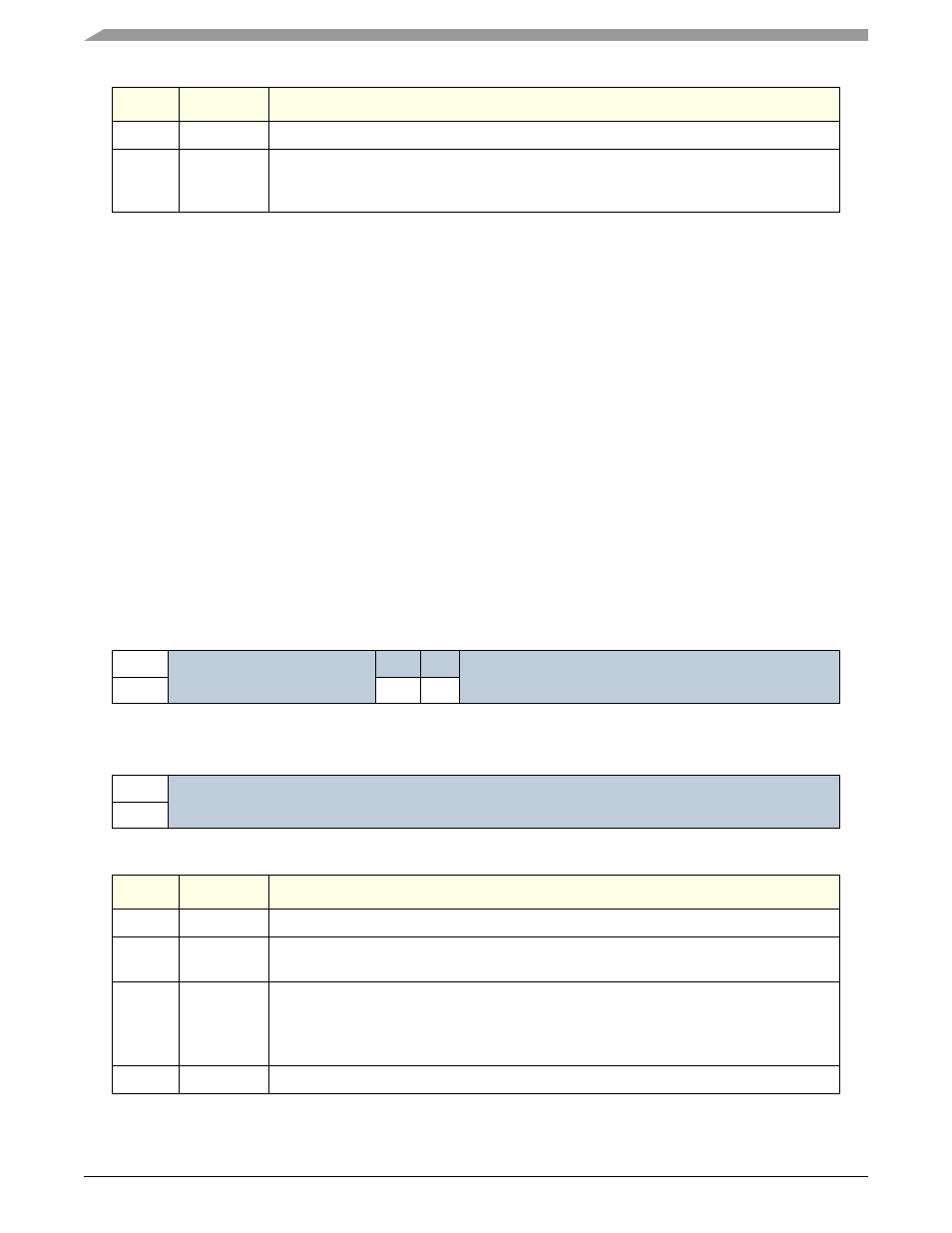
Table 11-19. ATA Drive Device Control Register
msb 0
1
2
3
4
5
6
7
8
9
10
11
12
13
14
15
R
Reserved
Reserved
W
SRST
nIEN
RESET:
0
0
0
0
0
0
0
0
0
0
0
0
0
0
0
0
16
17
18
19
20
21
22
23
24
25
26
27
28
29
30
31 lsb
R
Reserved
W
RESET:
0
0
0
0
0
0
0
0
0
0
0
0
0
0
0
0
Bits
Name
Description
0:4
—
Reserved
5
SRST
Software Reset—Host controlled software reset bit. Drive executes software reset protocol
when bit is set to 1 by host.
6
nIEN
Interrupt Enable—Host controlled interrupt enable. INTRQ is enabled when this bit is cleared
to 0.
Note: NOTE: For MPC5200B ATA Host Controller, enabling INTRQ is mandatory for
DMA/UDMA data transfer modes.
7:31
—
Reserved