Rockwell Automation 5370-CVIM2 Module User Manual
Page 93
5
Chapter
Chapter 4
Inspection Configuration
4–7
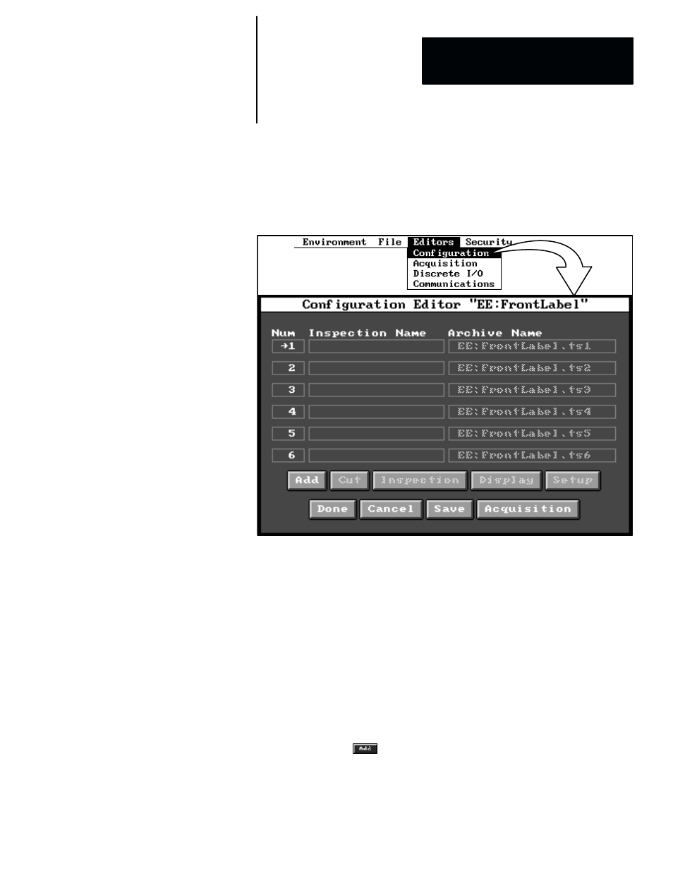
Assuming that at least one configuration has been set up and selected, when
you then pick
Editor
in the main menu bar, and then pick
Configuration
in
the
Editor
menu, the
Configuration Editor
panel appears, as shown in
Figure 4.6.
Figure 4.6 Example: Configuration Editor Panel With Six Inspections
ЗЗЗЗЗЗЗЗ
ЗЗЗЗЗЗЗЗ
ЗЗЗЗЗЗЗЗ
ЗЗЗЗЗЗЗЗ
Note that the configuration editor panel contains several data entry fields and
“buttons.” Here is a brief description of their functions:
•
Num –– This field contains the number of a “toolset,” such as 1, 2, or 3.
(This number is fixed –– you cannot change it.)
•
Inspection Name –– The inspection name is used to identify a toolset for
I/O, communication, and display purposes. Use this field to select a name
(up to 15 characters) for a toolset. (The default inspection names for the
six toolsets are
Toolset 1
,
Toolset 2
, and so on
.
)
•
Archive Name –– The “archive name” identifies the device and file in
which the inspection tools are stored. Use this field to enter a name (up to
16 characters) of either a new file of inspection tools or an existing file of
inspection tools. (By default, the archive names for the six toolsets take
this form:
EE:config filename.ts1
,
EE:config filename.ts2
, and so on).
•
Add –– Use the
button to add new toolsets in the
Configuration
Editor
panel. (Alternatively, you can pick the inspection name field to
perform this function.)