Rockwell Automation 5370-CVIM2 Module User Manual
Page 232
5
Chapter
Chapter 6
Reference Tools
6–73
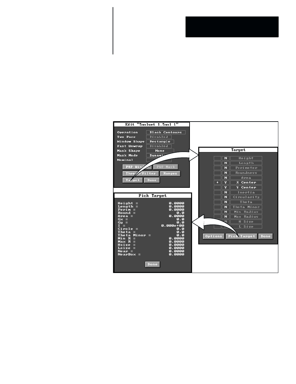
The window tool, using the
Black Contours
operation, is further configured
to supply the X–axis and Y–axis coordinates of the object’s centroid, and
theta, which is the angle between the object’s major axis and the X–axis of
the image field. These values result from the
X Center
,
Y Center
, and
Theta
parameters selected in the
Target
panel, as shown in Figure 6.62, and
are the reference values that the build reference formula will “learn” and use
during operation.
Figure 6.62 Example: Selecting Contour Parameters for Use in Build Reference Tool
ЗЗЗЗЗЗЗЗ
ЗЗЗЗЗЗЗЗ
ЗЗЗЗЗЗЗЗ
ЗЗЗЗЗЗЗЗ
ЗЗЗЗЗЗЗЗЗЗ
ЗЗЗЗЗЗЗЗЗЗ
ЗЗЗЗЗЗЗЗЗЗ
ЗЗЗЗЗЗЗЗЗЗ
ЗЗЗЗЗЗЗЗЗЗ
During operation, the task for the build reference tool in this example is to
calculate the difference, if any, between the “learned” theta angle and the
theta angle of the current inspected object, and to apply that angular
difference as rotation compensation to the two gage tools.
Initially, the build reference tool edit panel appears as it is shown in
Figure 6.57 (page 6–69). Note that “
Absolute
” is selected in the
X Mode
field, while the other mode fields are disabled. These are the default
selections for this tool edit panel.
Since the theta mode only is used in this example, the
X Mode
field must be
set to “
Disabled
”
and the theta mode enabled by selecting “
Absolute
” in the
Theta Mode
selection panel. Figure 6.63 (page 6–74) illustrates the general
method for making these selections.