Overview: reference line tool configuration – Rockwell Automation 5370-CVIM2 Module User Manual
Page 161
Chapter 6
Reference Tools
6–2
•
Refline X
′, Refline Y′ –– This button accesses the configuration panel for
either the X
′– or the Y′–axis of the reference line, according to the
selected operation.
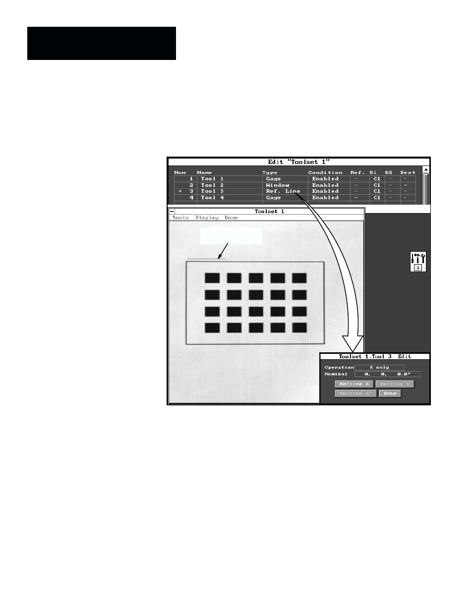
Figure 6.1
Example: Selecting the Reference Line Edit Panel
Reference line
(default position)
ЙЙЙЙЙЙЙ
ЙЙЙЙЙЙЙ
ЙЙЙЙЙЙЙ
ЙЙЙЙЙЙЙ
ЙЙЙЙЙЙЙ
ЙЙЙЙЙЙЙ
ЙЙЙЙЙЙЙ
ЙЙЙЙЙЙЙ
ЙЙЙЙЙЙЙ
ЙЙЙЙЙЙЙ
ЙЙЙЙЙЙЙ
ЙЙЙЙЙЙЙ
ЙЙЙЙЙЙЙ
ЙЙЙЙЙЙЙ
The remainder of this section discusses reference line tool configuration from
the perspective of the data fields and buttons in the reference line edit panel.
A reference line tool can be selected when the toolset edit panel is on the
screen. Starting from the main menu bar, the selection path to this panel is as
follows: Editors
→ Configuration → Setup → Tools. This selection path
is shown by the example in Chapter 7, Inspection Tools, Figure 7.2 (page
7–3).
Here is a summary of the basic reference line tool selection and configuration
steps, listed in their normal order of performance. These steps are common to
all six reference line tool operations (except as noted):
1. Select reference line tool operation –– select one of the six reference
line tool operations according to the application requirements.
Overview: Reference Line
Tool Configuration