Rockwell Automation 5370-CVIM2 Module User Manual
Page 307
5
Chapter
Chapter 7
Inspection Tools
7–69
In Figure 7.57, the
X Edge
kernel causes the gradient (edge) on the left side
of the inspected object to appear as a vertical line of light pixels, and the
right gradient (edge) to appear as a line of dark pixels. The pixels
surrounding the two gradients were converted to medium gray. (Compare the
results in this figure to the results of the
Sobel X
kernel in Figure 7.52 on
page 7–63.)
Note that the
Sign
LUT was selected for the example. Since the
X Edge
kernel creates a signed image, which contains pixel values between –128 and
+127, the
Sign
LUT removes negative values from the image by adding 128
to each value, thereby placing all pixel values in the 0 to 255 range that the
inspection tools require to identify and evaluate features properly.
Note also that the
Absolute
,
S.Threshold
, or
S.Clip
LUT could be used,
since they also remove negative values from the image. The choice of LUT
depends on the specific requirements for the application.
The effects on the inspected object that the
Absolute
and
S.Threshold
LUTs have when using the
X Edge
kernel would be similar to the
Sobel X
examples in Figure 7.53 (page 7–64). The main difference is that the
X Edge
kernel produces a wider gradient.
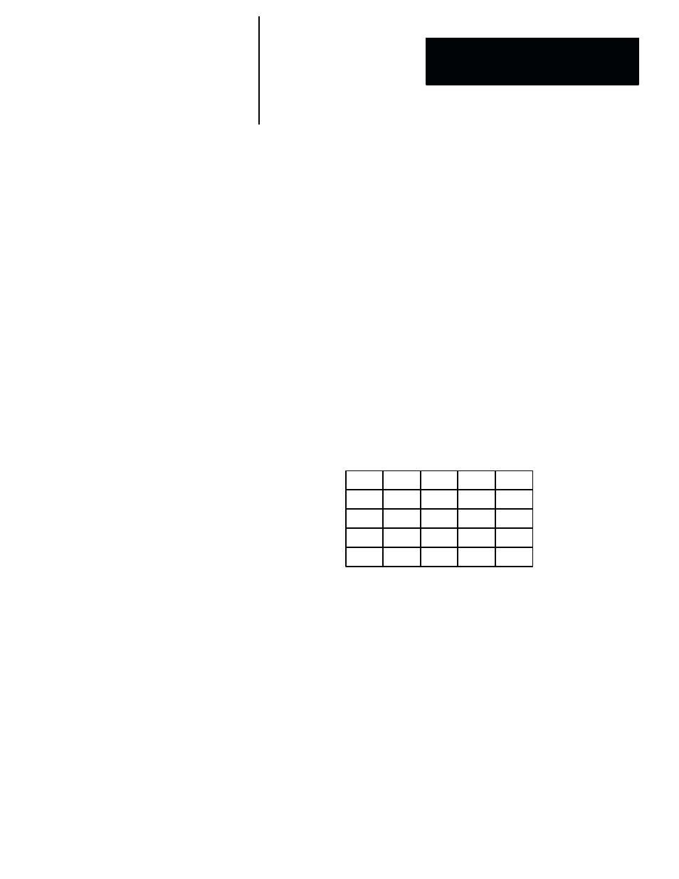
Y Edge Kernel –– The coefficients in the
Y Edge
kernel are arrayed as
follows:
1
1
1
0
2
0
2
1
1
0
1
4
2
0
0
–1
–2
–1
–4
–2
–1
–1
–2
–1
–1
Figure 7.58 (page 7–70) uses the inspected object shown in Figure 7.57 (page
7–68) to illustrate the effect of the
Y Edge
kernel.
In Figure 7.58, the
Y Edge
kernel causes the gradient (edge) on the top side
of the inspected object to appear as a horizontal line of light pixels, and the
bottom gradient (edge) to appear as a line of dark pixels. The pixels
surrounding the two gradients were converted to medium gray.
Note that the
Sign
LUT was selected for the example. Since the
Y Edge
kernel creates a signed image, which contains pixel values between –128 and
+127, the
Sign
LUT removes negative values from the image by adding 128
to each value, thereby placing all pixel values in the 0 to 255 range that the
inspection tools require to identify and evaluate features properly.
Note also that the
Absolute
,
S.Threshold
, or
S.Clip
LUT could be used,
since they also remove negative values from the image. The choice of LUT
depends on the specific requirements for the application.