Reference line tool configuration – Rockwell Automation 5370-CVIM2 Module User Manual
Page 169
Chapter 6
Reference Tools
6–10
This section discusses the configuration steps that are accessed from the
Refline
buttons in the reference line tool edit panel. Note that the
Refline
buttons that are active (white type) at any one time depend on the currently
selected operation. Thus when X only is selected, for example, only the
button is active.
For the purposes of this discussion, the
X’, X then Y
three–axis reference
line tool operation is assumed to have been selected in the
Refline
Operation
selection panel (Figure 6.2, page 6–3), and the reference line
edit panel is displayed on the screen as shown in Figure 6.9.
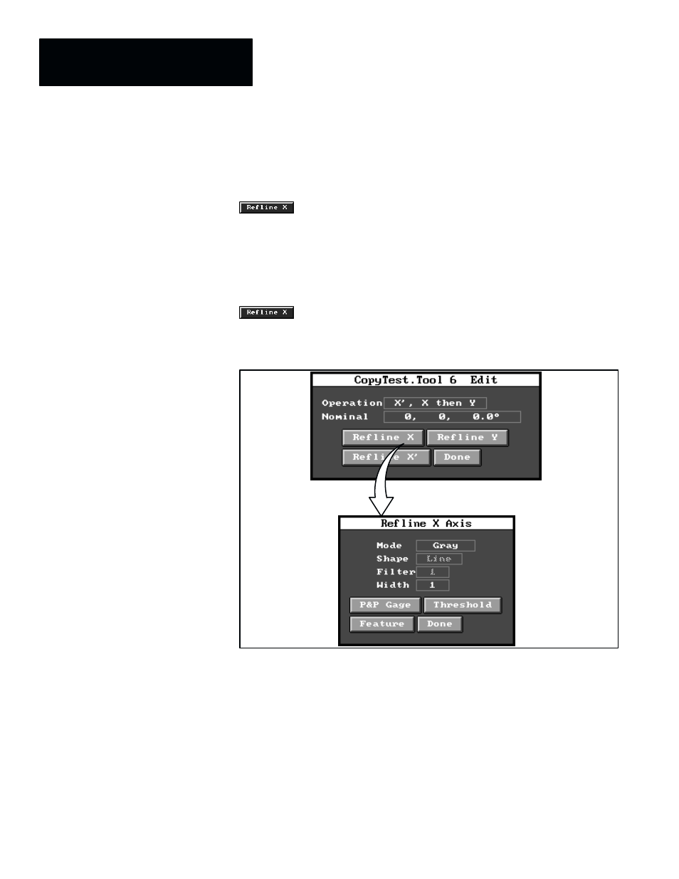
From that starting point, the configuration process begins when you pick the
button on the reference line edit panel and the
Refline X–axis
configuration panel appears, as shown in Figure 6.9.
Figure 6.9 Selecting the Refline X–axis Configuration Panel
ЗЗЗ
ЗЗЗ
ЗЗЗ
ЗЗЗ
ЗЗЗ
The
Refline X–axis
and
Refline Y–axis
configuration panels (not shown)
contain the same data fields and buttons as the
Refline X–axis
panel in
Figure 6.9, above. Thus, the following descriptions of apply to all three of
these axis configuration panels.
•
Mode –– This field enables the selection of either the binary edge
detection or the gray scale edge detection.
•
Shape –– This field is inactive (shaded type) for reference line tool
purposes, since there is no circular or “arc” reference line tool.
Reference Line Tool
Configuration