Linear gages – Rockwell Automation 5370-CVIM2 Module User Manual
Page 132
Chapter 5
Pick and Place Function
5–2
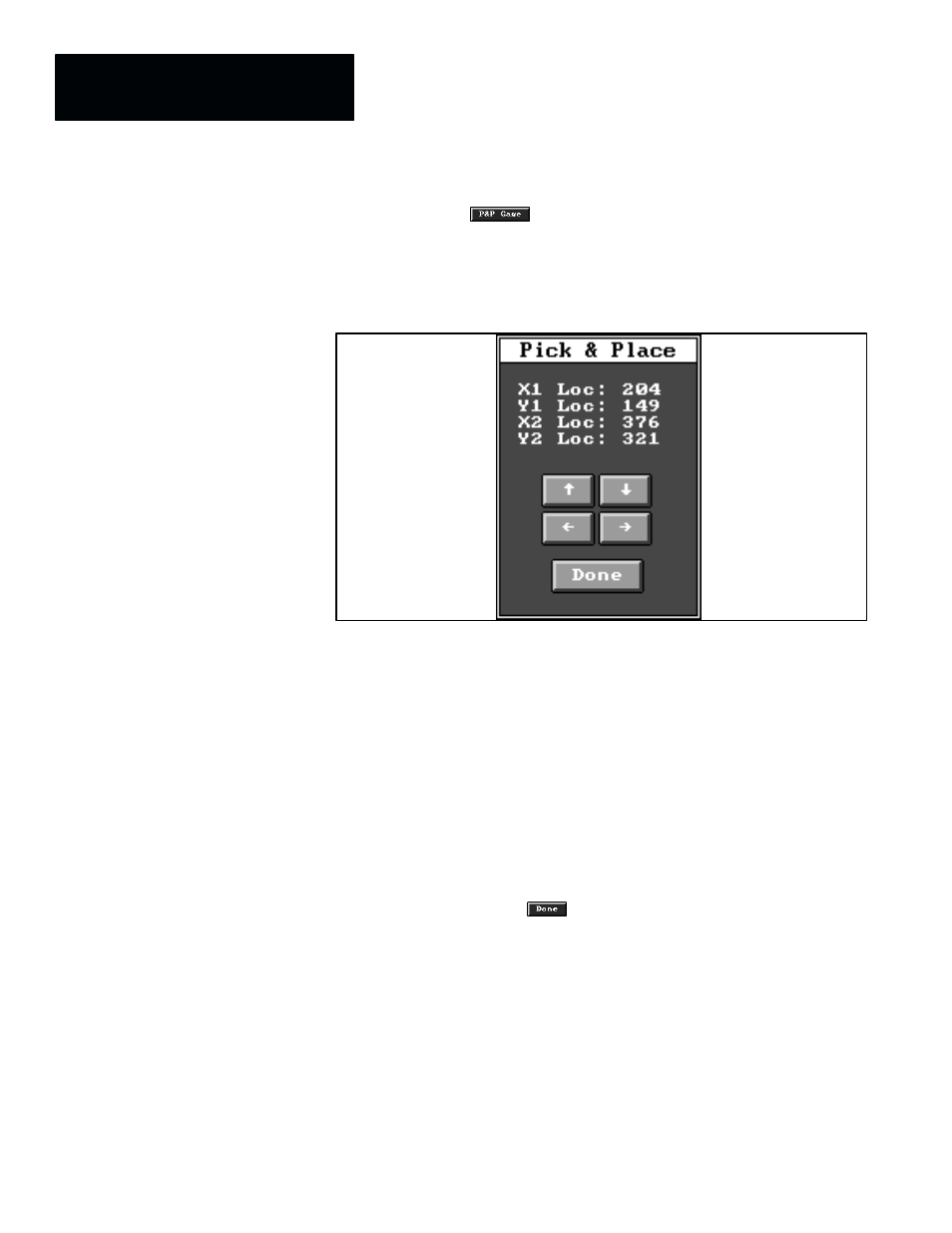
When you pick the
button in the gage edit panel (during setup
mode) or the gage adjust panel (during online operation), the gage color
changes from red to green, and the
Pick & Place
panel appears, as shown in
Figure 5.1.
Figure 5.1 Example: Pick and Place Panel for a Line
The
Pick & Place
panel for the line gage contains the following data display
fields and buttons:
•
X1 Loc; Y1 Loc –– These two fields display, respectively, the current X
and Y coordinates of the “head” of the gage.
•
X2 Loc; Y2 Loc –– These two fields display, respectively, the current X
and Y coordinates of the “tail” of the gage.
•
Arrow buttons,
↑, ↓, ←, and → –– When you pick an arrow button, by
default the entire line moves one pixel in the direction of the
corresponding arrow. If, however, you have just picked and placed the
“head” or “tail” of the line, the arrow buttons will then affect that part of
the line only.
•
Done –– When you have set the line’s position and size as required for
the application, pick the
button to exit the pick and place function
and return to the tool edit or adjust panel.
The green gage color indicates that the gage is enabled for pick and place
operations. Figure 5.2 (page 5–3) demonstrates the pick and place operation
as it pertains to a linear gage. Using pick and place, you can change the
length and angle of a linear gage and position the gage anywhere, so long as
it lies entirely within the image field.
NOTE: Before using the buttons, you must first “click” the light pen or
mouse pointer anywhere outside the image display panel (except in the A–B
“Help” icon) in order to “activate” the
Pick & Place
panel. The panel is
active when its border changes to solid black.
Linear Gages