Rockwell Automation 5370-CVIM2 Module User Manual
Page 189
Chapter 6
Reference Tools
6–30
Active Feature Selection
For the purposes of this discussion, the configuration process begins with the
selection of the “active feature”; that is,
Feature A
or
Feature B
. The
selected feature is “active” for the purposes of configuration.
Feature Image Configuration
The next step is the configuration and selection of a feature image (or no
image, which disables the feature). A feature image is a “template,” stored in
a file, that the reference window tool uses to locate a specific feature in the
search window. This step is initiated when you pick the
Image Name
field
in the reference window tool edit panel (see Figure 6.24).
Selecting Image Manager Panel
When you pick the
Image Name
field in the tool edit panel, the
Image
Manager
panel appears, as shown in Figure 6.25.
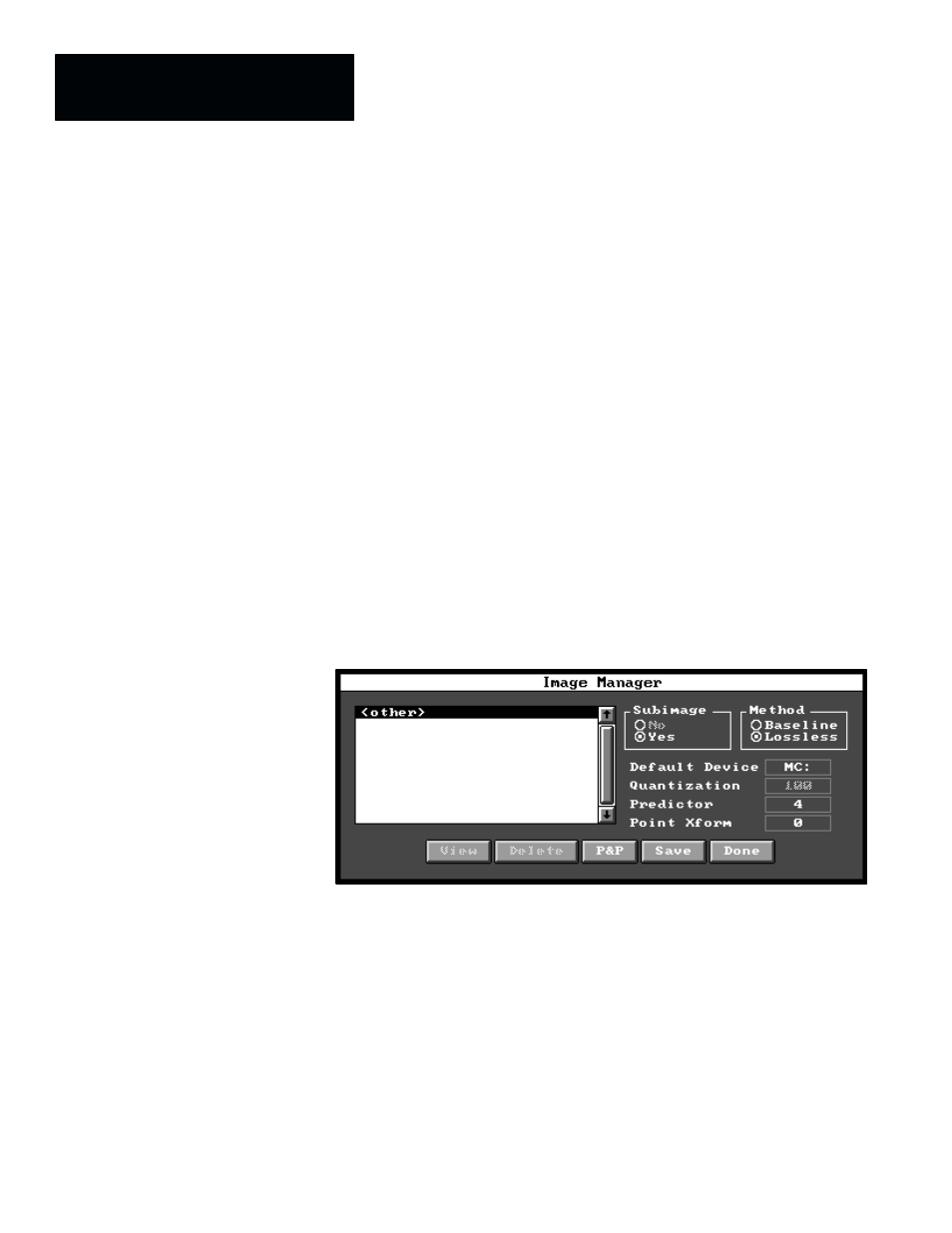
Figure 6.25 Selecting Image Manager Panel
The function of the
Image Manager
panel is to provide a number of choices
for compressing and storing images. (This panel is discussed in detail in
Chapter 4, Inspection Configuration, under the Image Manager Panel
heading on page 4–40.)
As it is used with reference windows, the
Image Manager
panel is restricted
to compressing and storing subimages only. Also, the “
Lossless
” (default)
compression method is normally used since reference window feature images
are usually quite small, and compressing them further does not save a
significant amount of memory. Furthermore, any loss of feature image data
(that would result from using the “
Baseline
” compression method) may
make the operation of the reference window less reliable. Finally, the
Predictor
and
Point Xform
selections should remain at their default values
of 4 and 0, respectively.