Rockwell Automation 5370-CVIM2 Module User Manual
Page 319
5
Chapter
Chapter 7
Inspection Tools
7–81
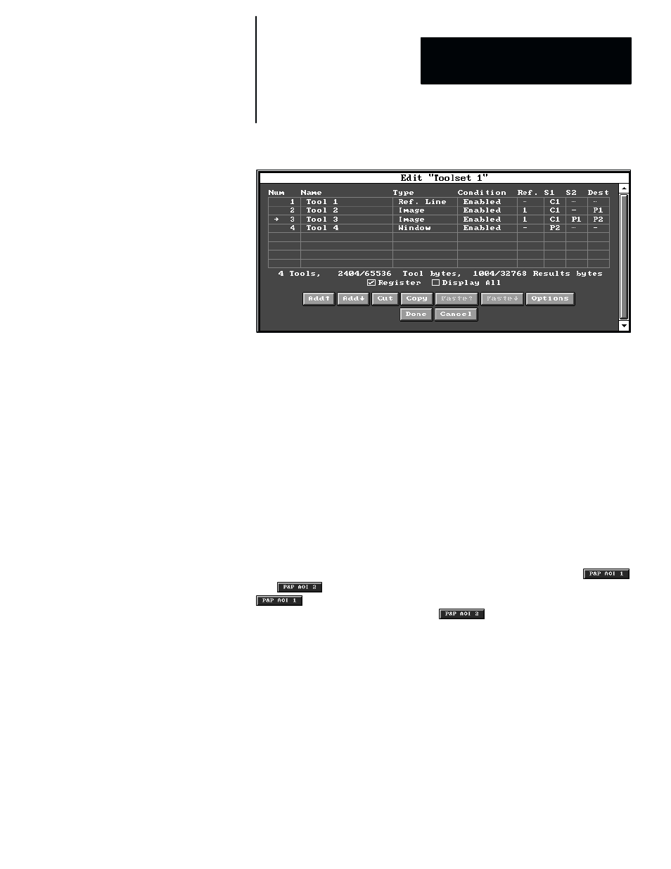
Figure 7.65 Example: Designating S2 Source for Image Tool Using S1 – S2
In this example,
Tool 2
is an image tool that is configured to process an AOI
within an image whose source is camera #1 (designated by “
C1
” in the “
S1
”
column) and deliver the processed image to a destination image buffer
(designated by “
P1
” in the “
Dest
” column).
Tool 3
is an image tool that is configured for the
S1 – S2
image subtraction
operation. Its primary image source is camera #1 (designated by “
C1
” in the
“
S1
” column). Its secondary image source is the destination image buffer
containing the processed image from
Tool 2
(designated by “
P1
” in the “
S2
”
column). The destination for
Tool 3
’s processed image is a different
destination image buffer (designated by “
P2
” in the “
Dest
” column).
Tool 4
is a window tool. Its primary (and only) image source is the
destination image buffer (designated by “
P2
” in the “
S1
” column) that
contains the results of the image subtraction operation performed by the
preceding image tool,
Tool 3.
When the
S1 – S2
subtraction operation is selected for
Tool 3
, the
and
buttons both become active in the tool edit panel. The
button accesses the “pick and place” function for AOI#1, which
relates to image source
S1
, while the
button accesses the “pick and
place” function for AOI#2, which relates to image source
S2
.
Initially, AOI#1 appears in its default position in the upper–left part of the
screen. The image content within AOI#1 at this point depends on whether
any part of AOI#2 lies outside its source image (which is from the AOI in
Tool 2
, in this example). If not, the contents of AOI#1 will immediately
display a processed image from the
S1 – S2
subtraction; if so, the contents
of AOI#1 will remain unchanged. (See the Image Tool Operations: Warning
Messages section, on page 7–84, for a discussion of the automatic
adjustments that the CVIM2 system performs on the AOI’s under some
circumstances, and the related “warning” messages.)
AOI#1 and AOI#2 can be resized and/or positioned at this time by picking
their respective “
P&P
” buttons to access their pick and place functions.