Rockwell Automation 5370-CVIM2 Module User Manual
Page 57
Chapter 3
Image Acquisition Parameters
3–18
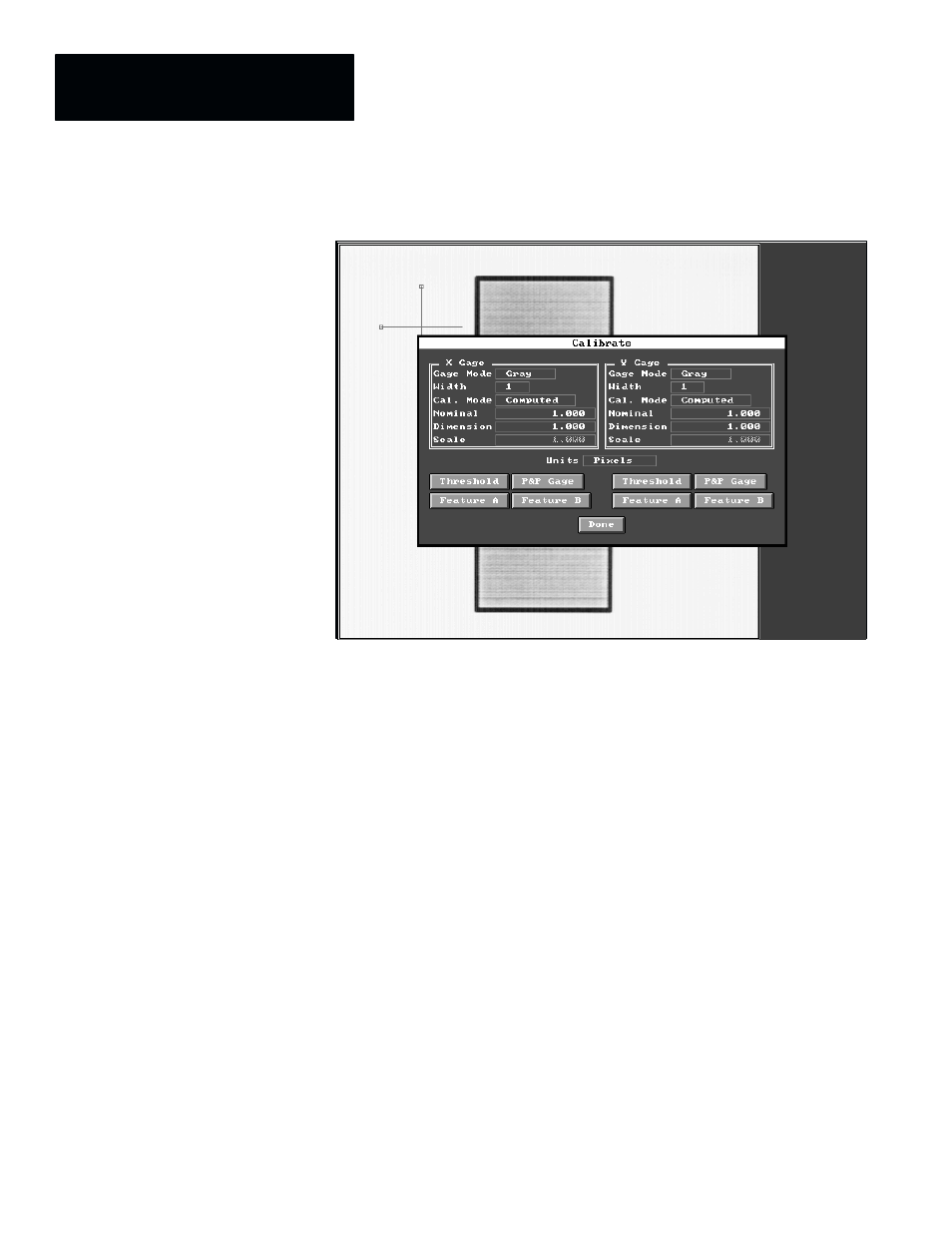
Figure 3.11 Calibrate Panel With X and Y Axis “Gages”
A calibration “gage” is essentially the same as a linear gage tool, but it has a
few limitations that are appropriate to its use in the calibrate function.
The
Calibrate
panel has two sets of identical parameter selection fields and
function selection buttons for the X–axis and Y–axis gages. These selection
fields and buttons are described briefly, as follows:
•
Gage Mode –– This field selects either the gray scale mode or the binary
mode of edge detection for the corresponding axis. Generally, you should
select the same gaging mode for the calibrate gages and the gage tools in
your application. The default gage mode is
Gray
. To change the gage
mode, pick the gage mode field.
•
Width –– This field provides access to the selection of the gage width.
The default setting is 1.
•
Cal. Mode –– This field selects either the
Computed
calibration mode or
the
Absolute
calibration mode. The default is
Computed
. To change the
calibration mode, pick the
Cal.Mode
field.
•
Nominal –– When you pick this field, the corresponding gage performs a
linear measurement in pixels, with the results appearing in this field. The
default value is 1.000.
•
Dimension –– Use this field to calibrate the X–axis or Y–axis by entering
the actual dimension of the calibration object in “world units.”