Rockwell Automation 5370-CVIM2 Module User Manual
Page 205
Chapter 6
Reference Tools
6–46
In example (A), the difference between 55 and 47 is 8. Since this pixel error
is equal to the “
Ignore
” parameter, it is ignored. For the remaining pixels,
the differences are 9, 15, and 14, respectively. Since all of these pixel errors
are higher than 8, they are recognized. The squares are 81, 225, and 196, and
the sum of these squares is 502. Since the feature image contains four pixels,
502
4 = 125.5. The square root of 125.5 is 11.2, which exceeds the “
Max.
RMS
” parameter. Thus, at this point in the search operation, a match does
not occur.
Example (B) illustrates an acceptable match, since the calculated RMS is less
than the “
Max. RMS
” parameter. Example (C) illustrates a perfect match,
with the calculated RMS at 0.0.
Starting with the “
Max. RMS
” parameter set to the default value (64), one
method for determining the most appropriate RMS parameter value for your
application is to select “
Best
” in the “
Stop When
” selection field and then
perform a
Nominal
or “learn” operation as described in the Nominal
(“Learn”) Function section. This will calculate the RMS value for the best
template match.
The “
Max. RMS
” parameter value should be set slightly higher, initially,
than the “
Best
” calculated value, and tool operation should be evaluated
using this value. The final value, however, should be the one that provides
the most reliable template matching under the operating conditions of your
application. This means, ideally, that the reference window should always
find the correct feature when it is in the search window, and should never
falsely identify a different feature.
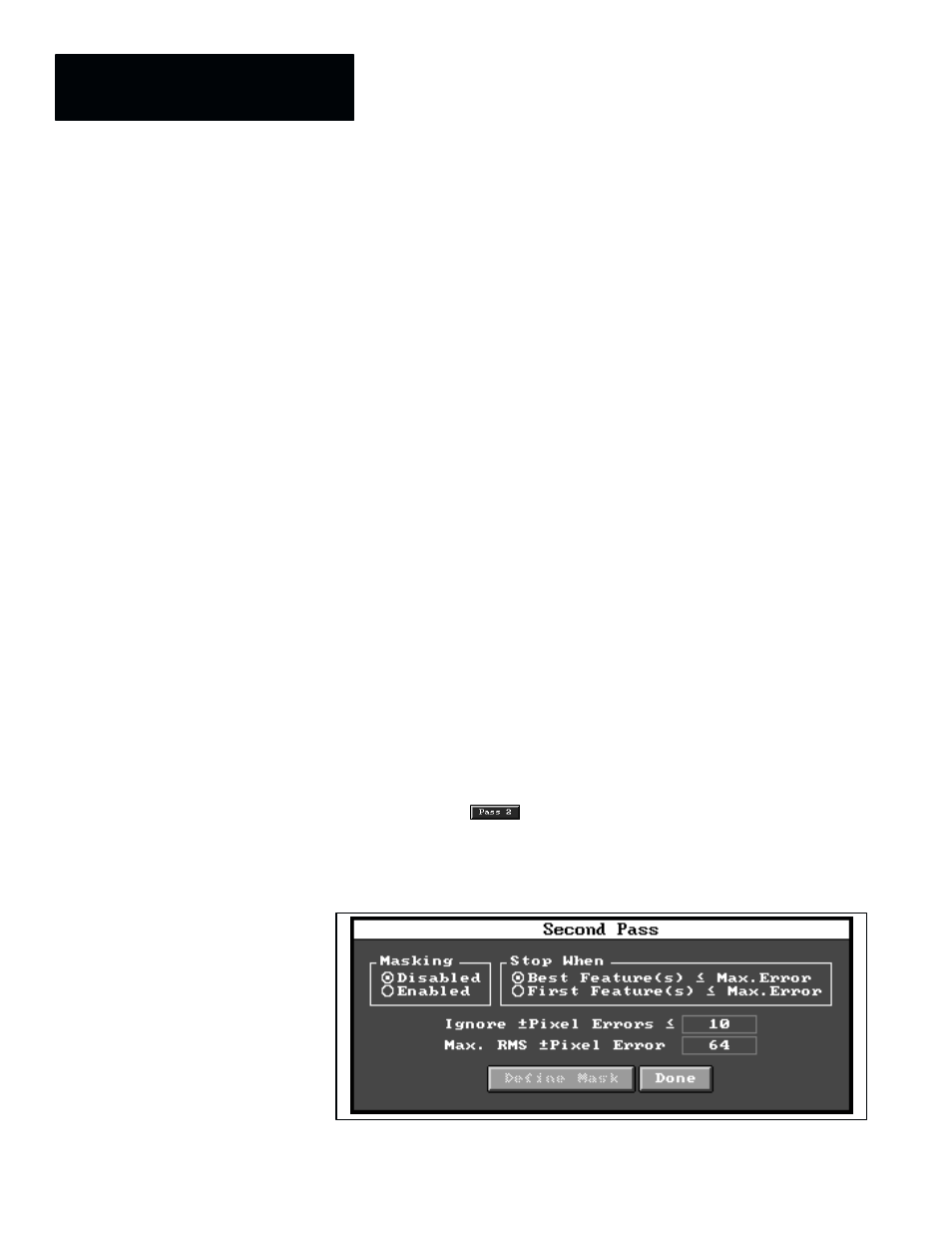
Second Pass Configuration
When you pick the
button in the reference window tool edit panel,
the
Second Pass
configuration panel appears on the display, as illustrated
in Figure 6.39. (Also appearing are the feature and search images.)
Figure 6.39 Example: Second Pass Configuration Panel