Image tool direction – Rockwell Automation 5370-CVIM2 Module User Manual
Page 334
Chapter 7
Inspection Tools
7–96
•
Threshold –– This selection converts an “unsigned” gray scale image to a
binary image. All pixels whose gray values lie between the
user–selectable thresholds become white, while all other pixels become
black. Thresholds can be set to gray values ranging from 0 to 255.
•
S.Threshold –– This selection converts a “signed” image to a binary
image. All pixels whose gray values lie between the user–selectable
thresholds become white, while all other pixels become black. Thresholds
can be set to gray values ranging from –128 to 127.
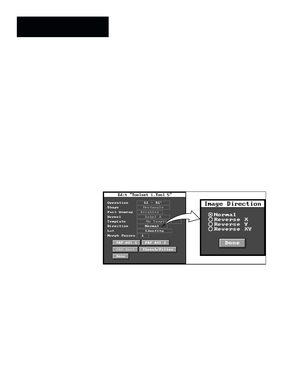
The
Direction
field in the tool edit panel, as noted earlier, is active only
when an image arithmetic operation is selected. This field accesses the
Image Direction
selection panel, which, enables you to select a different
scan direction for the secondary image (
S2
,
S1’
, or T). The scan direction
for the primary image (
S1
) is fixed: left–to–right, and top–to–bottom.
When you pick the
Direction
field in the image tool edit panel, the
Image
Direction
selection panel appears as shown in Figure 7.79.
Figure 7.79 Accessing the Image Direction Selection Panel
ЗЗЗЗЗ
ЗЗЗЗЗ
ЗЗЗ
ЗЗЗ
ЗЗЗ
Note that the default scan direction is
Normal
, which indicates that the scan
directions for the secondary and primary images are the same.
The selections in the
Image Direction
panel affect only the scan directions
for the secondary image. They are described briefly as follows:
•
Normal –– This scan direction is left–to–right and top–to–bottom.
•
Reverse X –– This scan direction is right–to–left and top–to–bottom.
•
Reverse Y –– This scan direction is left–to–right and bottom–to–top.
•
Reverse XY –– This scan direction is right–to–left and bottom–to–top.
A typical application for the reverse scanning function is to inspect for
symmetrical features.
Image Tool Direction