Chapter, Connecting the i/o and camera cables – Rockwell Automation 5370-CVIM2 Module User Manual
Page 17
5
Chapter
Chapter 1
Hardware Connection and Powerup Check
1–5
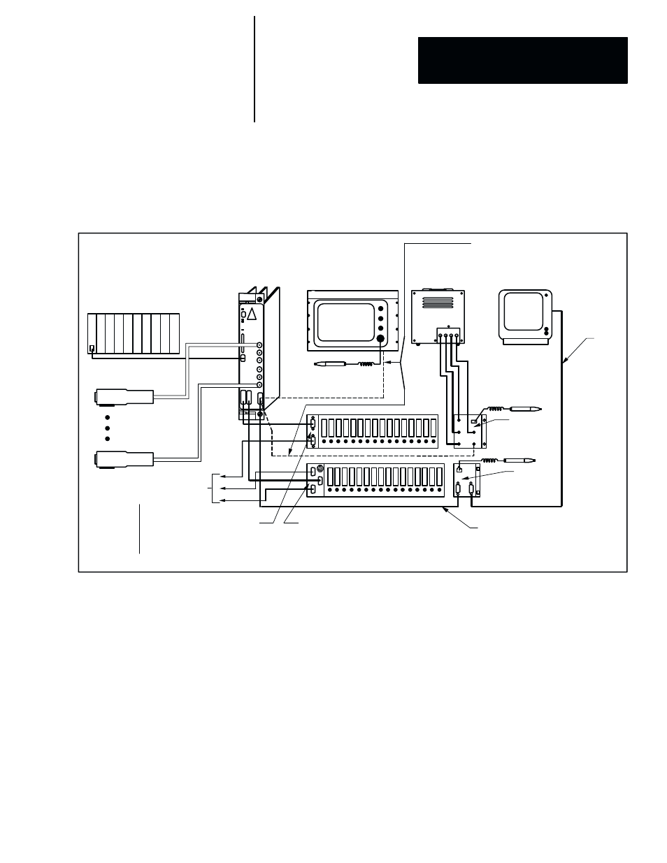
Connecting the I/O and Camera Cables
Refer to the CVIM2 interconnect diagram (Figure 1.2) for the I/O and
camera cable connections in the next steps.
Figure 1.2 CVIM2 Interconnect Diagram for I/O Cables
S
М
М
М
М
М
М
М
MACHINE VISION CAMERAS
2801–YB
2801–YD
2801–YE
2801–YC
CABLES
CABLES
2801–NC5 (5M)
2801–NC6 (10M)
2801–NC7 (25M)
2801–NC14 (5M)
2801–NC15
(10M)
2801–NC16
(25M)
MONITOR INTERFACE
CABLES
2801–NC19A (5M)
2801–NC19B (10M)
2801–NC19C (25M)
ММ
ММ
ММ
ММ
ММ
ММ
ММ
ММ
ММ
С
С
MACHINE VISION
CAMERA 6
М
М
ММ
ММ
М
М
М
М
ММ
ММ
М
М
М
М
М
М
М
М
М
М
М
М
М
М
ММ
М
С
MACHINE VISION
CAMERA 1
ММММММММ
ММММММММ
ММММММММ
ММ
ММ
ММ
М
М
М
М
М
М
ММ
ММ
ММ
ММММММММ
ММММММММ
ММММММММ
ММ
ММ
ММ
ММ
М
М
М
М
М
RS – 232
SERIAL COMMUNICATIONS
ММММММ
ММММММ
ММММММ
ММММММ
М
ALLEN–BRADLEY
ММММММ
ММММММ
ММММММ
ММММММ
МММММ
МММММ
МММММ
1771 CHASSIS
ММММММ
ММММММ
ММММММ
ММММММ
М
М
P
L
C
ММММ
ММММ
ММММ
ММММ
МММ
МММ
МММ
МММ
VGA
УУУУУУУ
УУУУУУУ
УУУУУУУ
УУУУУУУ
REMOTE I/O LINK
М
УУУУУУУ
УУУУУУУ
УУУУУУУ
УУУУУУУ
УУУУУУУ
УУУУУУУ
М
М
М
М
ММ
М
ММ
М
М
М
М
М
ММ
М
2801–NC17
2801–NC17
VGA MONITOR
INTERFACE CABLES
2801–NC20A (5M)
2801–NC20B (10M)
2801–NC20C (25M)
MODULE
I/O INTERFACE
2801–N21
2801–JMB
2801–JMB
USER
INTERFACE
2801–N26
LIGHT PEN
2801–N7
LIGHT PEN
2801–N7
2801–N8, –N8V
5370–CVIM2
R G B S
COLOR
MONITOR
USER
SUPPLIED
CABLE
М
М
М
М
ММ
ММ
М
М
М
М
М
М
MODULE
I/O INTERFACE
2801–N27
ММ
ММ
R
G
B
IN
CABLES
2801–NC2 (5M)
2801–NC3 (10M)
ММ
М
М
М
М
М
М
М
LIGHT PEN
2801–N7
USER
INTERFACE
2801–N22
LP
М
М
М
М
М
М
ММ
ММ
ММ
М
М
М
ММ
ММ
ММ
М
М
М
М
М
М
М
М
М
М
М
М
ММ
ММ
ММ
М
М
М
ММ
ММ
ММ
М
М
М
М
М
М
М
М
М
М
М
М
М
М
М
М
М
М
ММ
ММ
М
М
ММ
ММ
М
М
М
М
М
М
М
М
М
М
М
М
ММ
ММ
М
М
ММ
ММ
М
М
Connecting the I/O Interface Cable (2801–NC17, –NC17A)
Use the following steps to connect the I/O interface cable to the I/O interface
module:
1. Locate the I/O interface cable, Catalog No. 2801–NC17 or –NC17A, and
the I/O interface module, Catalog No. 2801–N21 or –N27.
NOTE: The two ends of this cable are identical.
2. Connect either end of the cable to the
Module I/O
(or
System I/O
)
connector on the CVIM2 front panel. Tighten the screws.
3. Connect the other end of the cable to the
CVIM
connector on the I/O
interface module. Tighten the screws.
NOTE: The I/O interface cable can be connected directly from the CVIM2
module to I/O interface module 2801–N28 on the 2801–AM2 vision chassis.