Conditional processing – Rockwell Automation 5370-CVIM2 Module User Manual
Page 421
5
Chapter
Chapter 7
Inspection Tools
7–183
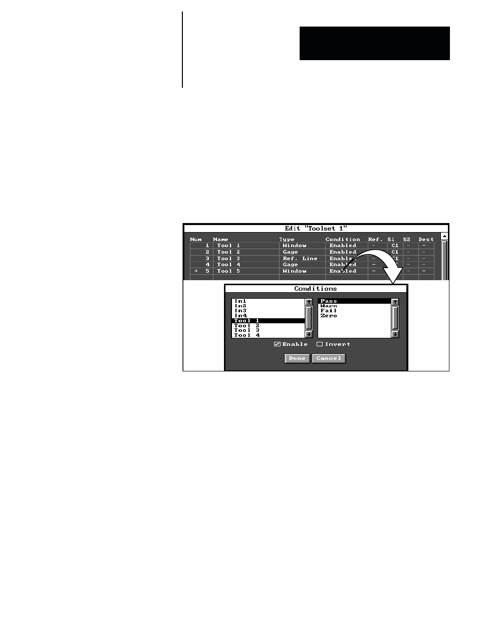
This section discusses “conditional processing,” which, when selected for a
specific inspection tool, permits that tool to execute only when a specific
“condition” (such as an active input signal, or a “pass” tool result) is
satisfied. The main effect of conditional processing is this: When the
specified condition is satisfied, the tool executes; when the condition is not
satisfied, the tool does not execute.
Conditions are selected from the
Conditions
panel, which can be accessed
from the toolset edit panel by picking the
Condition
field for a specific tool,
as illustrated by the example in Figure 7.147.
Figure 7.147 Example: Accessing Conditions Panel
ЗЗЗЗЗЗ
ЗЗЗЗЗЗ
ЗЗЗЗЗЗ
ЗЗЗЗЗЗ
The
Conditions
panel in Figure 7.147 illustrates the basic condition
selections, which are described briefly, as follows:
•
In1 – In4 –– The status of these inputs (that is, logic “0” or logic “1”) can
be used to determine whether or not the corresponding “conditional” tool
will execute. (Note that when any of these inputs are selected for
conditional use, they must also be defined in the Discrete I/O panel. Refer
to the In1 – In4 Input Selection section, on page 9–6 of Chapter 9, for
more information.)
•
Tool n –– This indicates the name of a specific tool, whose status
determines whether or not the corresponding “conditional” tool will
execute. (The
Tool n
selections must always include a selection from the
second list.)
•
Pass, Warn, Fail, Zero –– These selections specify the status of
Tool n
that will determine whether or not the corresponding “conditional” tool
executes. (Note that the “Zero” selection is not available for all tools; for
example, the reference line tool and the image tool.)
Conditional Processing