Rockwell Automation 5370-CVIM2 Module User Manual
Page 112
Chapter 4
Inspection Configuration
4–26
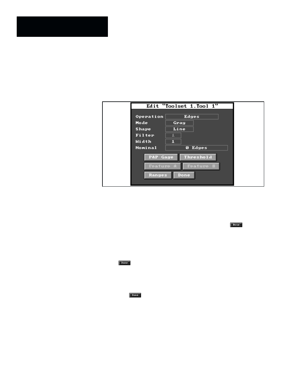
10. To access the tool for configuration purposes, pick the field with the tool
type in it (in this example, pick the “
Gage
” field). When you do, the
toolset edit panel is replaced by the tool edit panel, as shown in
Figure 4.21.
Figure 4.21 Example: Tool Edit Panel for Gage
NOTE: The default parameters in this example tool edit panel pertain to
the “
Gage
” inspection tool. At this point in the configuration process
you would configure this specific inspection tool. (Chapter 7, Inspection
Tools, contains all of the configuration details for gages and other
inspection tools.)
11. After you finish configuring the inspection tool, pick the
button.
When you do, the toolset edit panel reappears over the image/tool
display panel.
12. If you need to configure additional inspection tools, repeat step 8.
through step 11. as many times as needed to configure all required tools.
13. When you have completed all of the required tool configurations, pick
the
button on the toolset edit panel to save all newly configured
inspection tools in the toolset archive file. When you do, the toolset edit
panel disappears.
14. Pick
Done
in the menu bar of the image display panel. When you do, the
display panel disappears and the
Configuration Editor
panel reappears.
15. Pick the
button in the
Configuration Editor
panel. When you do,
the
Configuration Editor
disappears, and the configuration file is saved.
This completes the procedure for creating a configuration file.