Direction, Filter 1 and filter 2, Direction filter 1 and filter 2 – Rockwell Automation 5370-CVIM2 Module User Manual
Page 400
Chapter 7
Inspection Tools
7–162
The profile tool performs its operations along either the X–axis or the
Y–axis, as determined by the selection in the
Direction
field of the tool edit
panel.
When the “
X
” direction is selected, the profile tool calculates the average
gray scale value of each column of pixels within the profile window and
draws a graph or “profile” of the average values along the X–axis.
When the “
Y
” direction is selected, the profile tool calculates the average
gray scale value of each row of pixels within the profile window and draws a
graph or “profile” of the average values along the Y–axis.
For more information about direction, refer to the Profile Display section on
page 7–151.
The
Filter 1
and
Filter 2
fields provide access to several morphology
filtering functions that affect the profile image. Each filter field provides
access to a
Filter
selection panel, and each panel contains an identical list of
morphology functions.
When filtering functions are selected from both filter fields, the effect on the
profile display is cumulative, with the
Filter 1
selection performing its
morphology filter function first. (For additional information about
morphology functions, refer to Chapter 8 of this manual under the following
headings: Morphology Function, page 8–13; Binary Morphology, page 8–16;
and Gray Scale Morphology, page 8–20.)
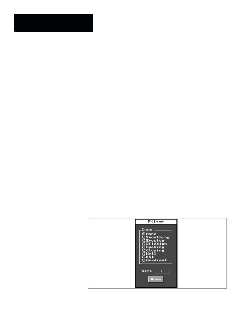
When you pick either filter field, the corresponding
Filter
selection panel
appears, as shown by Figure 7.132.
Figure 7.132 Example: Filter Selection Panel
Direction
Filter 1 and Filter 2