Rockwell Automation 5370-CVIM2 Module User Manual
Page 175
Chapter 6
Reference Tools
6–16
All edges –– The all edges feature mode enables you to specify a reference
point on a reference line axis from the following points on the axis:
•
All edges detected as a result of the threshold/filter settings.
•
The head of the axis when using the head–to–tail search direction, or the
tail of the axis when using the tail–to–head search direction.
•
The midpoints between adjacent pairs of edges.
•
The center point between the leading edge and the trailing edge on the
axis.
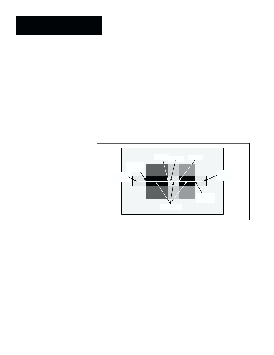
Figure 6.14 uses the binary gaging mode to illustrate the potential reference
points with the all edges feature mode.
Figure 6.14 Example: All Edges Along a Reference Line Axis
Center
“Head”
of axis
Edge
Midpoints
Leading
edge
Trailing
edge
“Tail”
of axis
Edge
Max Object –– The maximum object feature mode enables you to specify a
reference point on a reference line axis from the following points on the axis:
•
The leading edge of the maximum–size object along the axis.
•
The midpoint between the leading edge and the trailing edge of the
maximum–size object.
Figure 6.15 (page 6–17) uses both the binary gaging mode and the gray scale
gaging mode to identify the potential maximum object reference points.
Note in Figure 6.15 that the term “maximum object” has a different meaning
for binary and gray scale gaging modes, as follows:
Binary gaging mode –– The maximum object is the one with the greatest
number of consecutive white or black pixels between the first and last
detected edges on the axis. In example (A), above, leftmost object has the
greatest number of consecutive pixels, which are, in this case, black pixels.