Reference line tool operations – Rockwell Automation 5370-CVIM2 Module User Manual
Page 162
5
Chapter
Chapter 6
Reference Tools
6–3
2. Configure each axis:
a.
Select mode –– select either the binary mode or the gray scale
mode.
b. “Pick and place” –– position the axis over the workpiece as
required.
c.
Adjust thresholds –– adjust the binary (or gray scale) thresholds, as
required for edge detection.
d. Define features –– select the point that will be used to locate the
workpiece along the axis.
3. Learn nominal values –– perform a “learn” operation to store the
“nominal” values –– the data that indicate the workpiece’s initial
position.
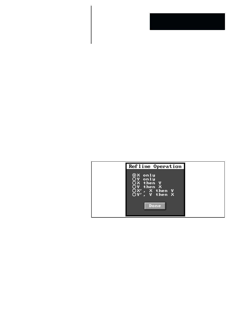
As noted earlier, there are six reference line tool operations, each of which
involves one, two, or three lines or “axes.” When you pick the
Operation
field in the reference line edit panel, the
Refline Operation
selection panel
appears, as shown in Figure 6.2.
Figure 6.2
The Refline Operation Selection Panel
The exact function that a reference line tool performs depends on which one
of the six “operations” has been selected. These operations use one, two, or
three reference line axes. The three–axis operation is capable of providing
rotation compensation.
Note that this selection panel lists the six reference line tool operations as
follows:
X only
and
Y only
, which use one axis;
X then Y
and
Y then X
,
which use two axes; and
X’ , X then Y
and
Y’ , Y then X
, which use three
axes. These operations differ mainly in the number of axes used and in the
order of their evaluation.
Table 6.1 (page 6–4) summarizes the reference line tool operations listed in
the
Refline Operation
selection panel.
Reference Line Tool
Operations