Camera type: selection and editing – Rockwell Automation 5370-CVIM2 Module User Manual
Page 72
5
Chapter
Chapter 3
Image Acquisition Parameters
3–33
After assigning the bank state status to the appropriate output, pick the
button to exit back to the
Acquisition System Settings
panel.
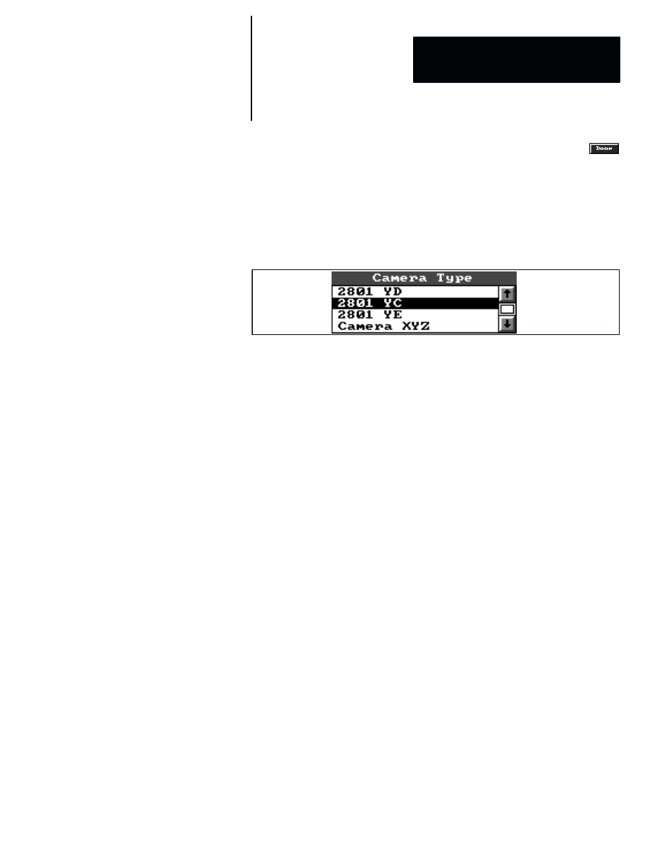
The
Camera Type
scrolling list, as shown in Figure 3.23, appears in two
places: the
Acquisition Editor
panel, and all of the
Camera
panels.
Figure 3.23 Example: Camera Type Scrolling List Panel
This list shows all of the “standard” cameras that the Allen–Bradley
Company supports, along with any number of non–standard cameras (such
as “
Camera XYZ
” in the example) that a user has configured for use with
the CVIM2 system.
The highlighted camera name in the scrolling list is the currently selected
camera type (
2801 YC
in the example). To select another name, just pick the
name. When you do, the new name is highlighted and the previous name is
unhighlighted.
In the
Acquisition Editor
panel, you can edit some of the selected camera’s
timing parameters, and you can copy a listed camera type to create a new
non–standard camera type under a different name.
In a
Camera
panel, the selected camera type should correspond to the type
that will be connected to the camera port whose number is shown in the
Camera
panel title bar (such as
“Camera 1”
). In addition, you can edit
some of the selected camera’s timing parameters.
Camera Type Edit Panel
The
Camera Type
edit panel contains several parameter selection boxes and
fields pertaining to the camera timing and scan modes for each camera type.
For the standard Allen–Bradley cameras (2801–YC, –YD, YE, and YF),
most of these parameters are inaccessible –– they cannot be changed. For
non–standard camera types, however, most of the parameters are accessible
and can be changed to whatever values are appropriate for a particular
non–standard camera.
Camera Type: Selection and
Editing