Rockwell Automation 5370-CVIM2 Module User Manual
Page 117
5
Chapter
Chapter 4
Inspection Configuration
4–31
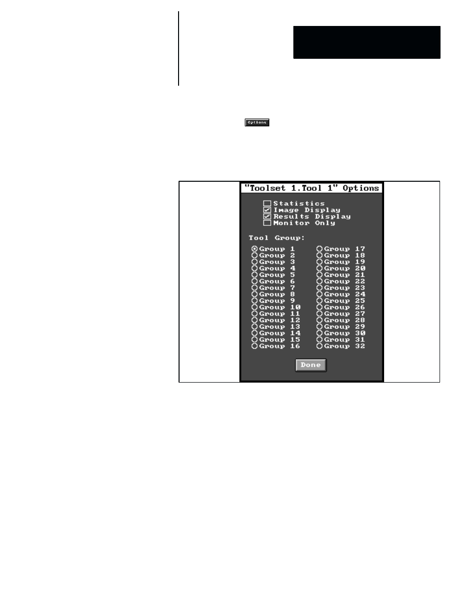
Options Selection Panel
When you pick the
button, the
Options
selection panel (for the
selected tool) appears, as shown by the example in Figure 4.23. Note that the
selected tool is indicated by the cursor arrow
〈→) in the
Num
field of the
toolset edit panel.
Figure 4.23 Example: Options Selection Panel
The first four options in the
Options
selection panel are enabled or disabled
by alternately picking the check box alongside each option. When a check
appears in a check box, the corresponding option is enabled, and the option
is disabled when the check box is empty. The options are described briefly as
follows:
•
Statistics –– When the
Statistics
function is enabled, statistics
calculations are performed for the currently selected tool. Note: The
Statistics
box is shaded for tools that do not support statistics
calculations (such as reference tools).
•
Image display –– When the
Image Display
function is enabled, the
graphics symbols for the currently selected tool appear in the image field
during inspection operations (setup mode and online).
•
Results display –– When the
Results Display
function is enabled, the
results data from the currently selected tool appear in the
Results
panel
during inspection operations (setup mode and online).
•
Monitor only –– When the
Monitor Only
function is enabled for a
particular tool, the “Pass/Fail” results from that tool are prevented from
affecting the “Pass/Fail” results for the corresponding toolset. You can use