Rockwell Automation 5370-CVIM2 Module User Manual
Page 409
5
Chapter
Chapter 7
Inspection Tools
7–171
When other threshold modes are selected, the slide bar assumes other
functions, which are discussed next in the Mode Selection section.
Mode Selection
When you pick the
Mode
field in the
Threshold
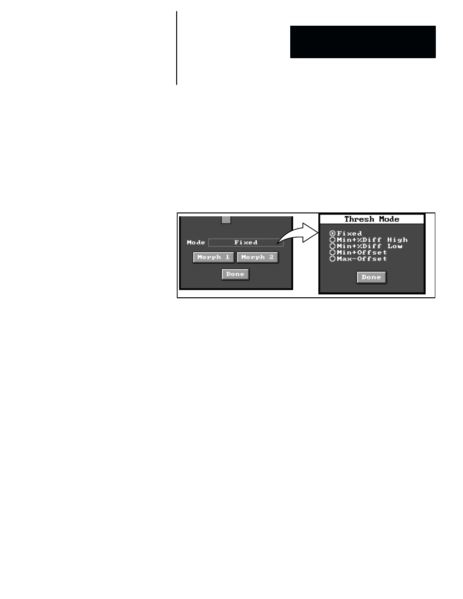
panel, the
Thresh Mode
selection panel appears, as shown in Figure 7.137.
Figure 7.137 Selecting Thresh Mode Panel
ЗЗЗЗЗ
ЗЗЗЗЗ
ЗЗЗЗЗ
The five threshold modes are described in the following sections.
Fixed Mode
This is the default threshold mode (see Figure 7.136, page 7–170), and it
indicates that the threshold will remain fixed at the value to which it was last
set by the
Threshold
slide bar or
Threshold
field entry. During the “
Fixed
”
threshold mode, the slide bar and field have the following functions:
•
Threshold slide bar –– The
Threshold
slide bar uses a single cursor to set
the threshold in relation to the profile image (and change the value in the
Threshold field).
•
Threshold field –– The
Threshold
field accesses a “calculator,” which
can be used to select a specific threshold value. The default value is 128.
The
Threshold
slide bar, and/or the value entered into the
Threshold
field,
affect the position of the threshold display as described in the Threshold
Display section on page 7–154. In either case, the threshold can be set to any
gray scale level within the range of 0 to 255 (which represents the lower and
upper limits of the profile image). Figure 7.125 and Figure 7.126 (page 7–154)
illustrate the threshold graphic at two different gray scale levels.