Gage tool – Rockwell Automation 5370-CVIM2 Module User Manual
Page 241
5
Chapter
Chapter 7
Inspection Tools
7–3
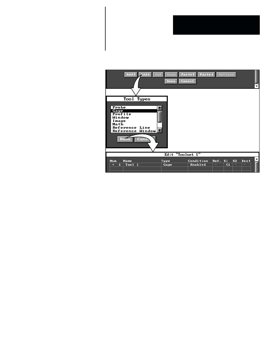
Figure 7.2
Example: Adding an Inspection Tool
ЗЗЗЗЗ
ЗЗЗЗЗ
ЗЗЗЗЗ
ЗЗЗ
ЗЗЗ
ЗЗЗ
ЗЗЗ
This section discusses line gage shapes, gaging modes, and the inspection
functions (“operations”) that the line gages can perform.
Once you have selected a gage as outlined in the Overview: Inspection Tool
Selection Process section (page 7–1), you can configure it for an inspection
application by picking the
Gage
field in the toolset edit panel. When you do,
the gage tool edit panel appears, as shown by the example in Figure 7.3 (page
7–4).
Note that in Figure 7.3 the gage is shown in its default shape (line) and
position on the screen.
The gage tool edit panel (named
Edit “Toolset 1.Tool 1”
in Figure 7.3)
contains several data fields and buttons, which are described briefly as
follows:
•
Operation –– This field provides access to the selection of one of the
gage “operations.” The default gage operation is
Edges
–– an
edge–counting operation.
•
Mode –– When you pick this field, the currently selected gaging mode
toggles to the other gaging mode. Thus,
Binary
toggles to
Gray
, and vice
versa. The default gaging mode is
Gray
.
•
Shape –– This field provides access to the selection of the gage shape,
which is
Line
, for a straight linear gage, or
Arc
, for a partially circular
gage, or
Circle
, for a fully circular gage. The default shape is
Line
.
Gage Tool