Rockwell Automation 5370-CVIM2 Module User Manual
Page 363
5
Chapter
Chapter 7
Inspection Tools
7–125
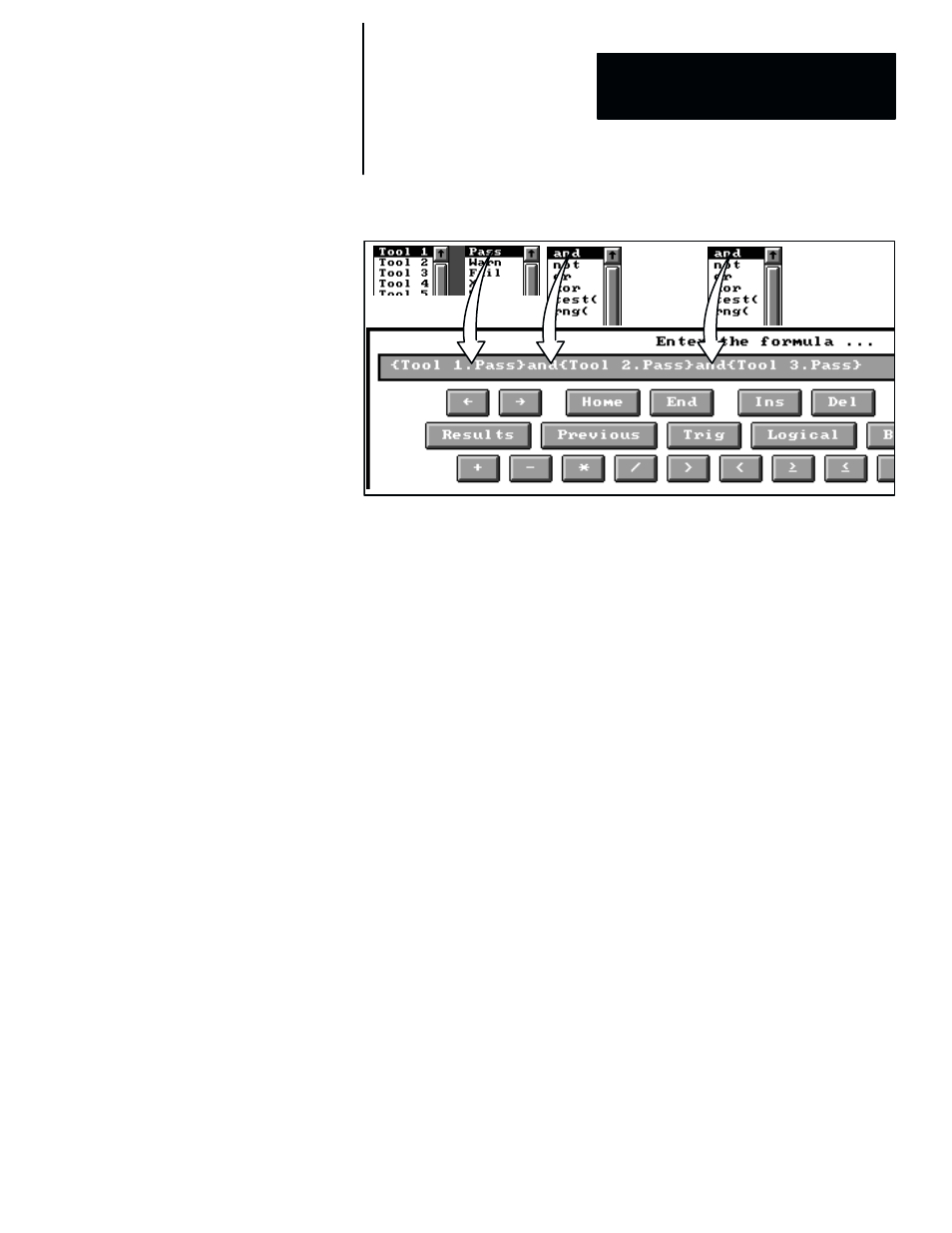
Figure 7.98 Example: Using a Logical “and” Function
ЗЗ
ЗЗ
ЗЗ
ЗЗ
ЗЗ
ЗЗ
ЗЗ
ЗЗ
ЗЗ
ЗЗ
ЗЗ
ЗЗ
ЗЗ
ЗЗ
ЗЗ
ЗЗ
ЗЗ
ЗЗ
In this example,
Tool 1.Pass
,
Tool 2.Pass
, and
Tool 3.Pass
will each yield
a logic “1” when the corresponding tool passes its inspection task. The
formula will yield a logic “1” when all three tools pass (and each yields a
logic “1”).
In another example, such as the following . . .
{Tool2}and{Tool3}
. . .
Tool 2
could be an object–counting window tool returning a count of 8,
and
Tool 3
could be a gage tool returning a linear measurement of 312.000
pixels. Since both of these inputs are non–zero, the formula in this case will
output a logic “1” result.
not –– The “
not
” logic operator is used with expressions containing other
logic operators, and its effect is to invert the normal logic result from such
expressions. It must be inserted ahead of the expression that it modifies.
Thus, if the “
not
” operator is appended to the example formula in
Figure 7.98, it will appear as follows . . .
not({Tool1.Pass}and{Tool2.Pass}and{Tool3.Pass})
In this example formula,
Tool 1.Pass
,
Tool 2.Pass
, and
Tool 3.Pass
will
each yield a logic “1” when the corresponding tool passes its inspection task.
The formula would normally yield a logic “1” when all three tools pass (and
each yields a logic “1”). The “
not
” operator, however, causes the normal
logic “1” result from the formula to be inverted to logic “0.”