9 - discrete i/o assignments, Discrete i/o editor panel: general information, Discrete i/o assignments – Rockwell Automation 5370-CVIM2 Module User Manual
Page 464
9
Chapter
9–1
Discrete I/O Assignments
This chapter provides detailed information about the discrete inputs and
outputs that connect the CVIM2 system to the user’s process control
equipment through the
Module I/O
,
System I/O
, and
Remote I/O
ports on
the CVIM2 module front panel. This chapter also includes the procedures for
assigning signals to the discrete inputs and outputs, the front panel LEDs and
the remote I/O inputs and outputs.
The
Module I/O
port contains two input and 14 output lines, while the
System I/O
port contains 16 discrete lines that the user can select as inputs
or outputs. The front panel contains two user–assignable status LEDs. The
Remote I/O
port provides 120 inputs to the CVIM2 from a PLC
, and 128
outputs to a PLC (the CVIM2 appears to a PLC as a full 8–slot rack on the
remote I/O line).
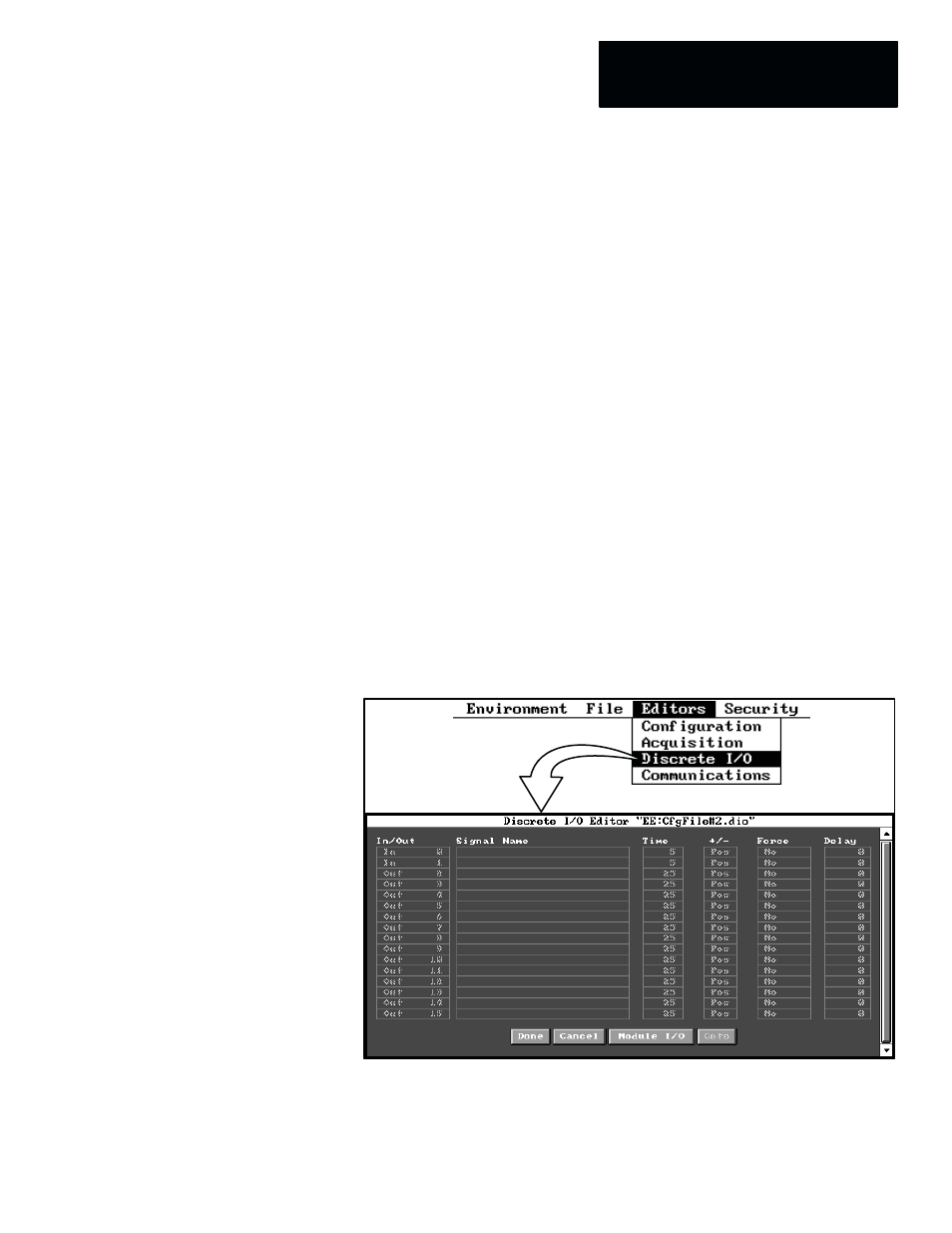
The discrete I/O assignments are performed in the
Discrete I/O Editor
panel. When you pick
Discrete I/O
in the
Editors
menu of the main menu
bar, the
Discrete I/O Editor
panel appears, as shown in Figure 9.1.
Figure 9.1 Selecting the Discrete I/O Edito
r
Panel (VGA Monitor)
ЗЗЗЗЗЗ
ЗЗЗЗЗЗ
ЗЗЗЗЗЗ
ЗЗЗЗЗЗ
NOTE: You can access this panel from various places within the
Configuration
and
Acquisition
editors, and there are differences in the types
of signal functions that you can assign, accordingly. These differences are
pointed out later in this chapter.
Discrete I/O Editor Panel:
General Information