Rockwell Automation 5370-CVIM2 Module User Manual
Page 362
Chapter 7
Inspection Tools
7–124
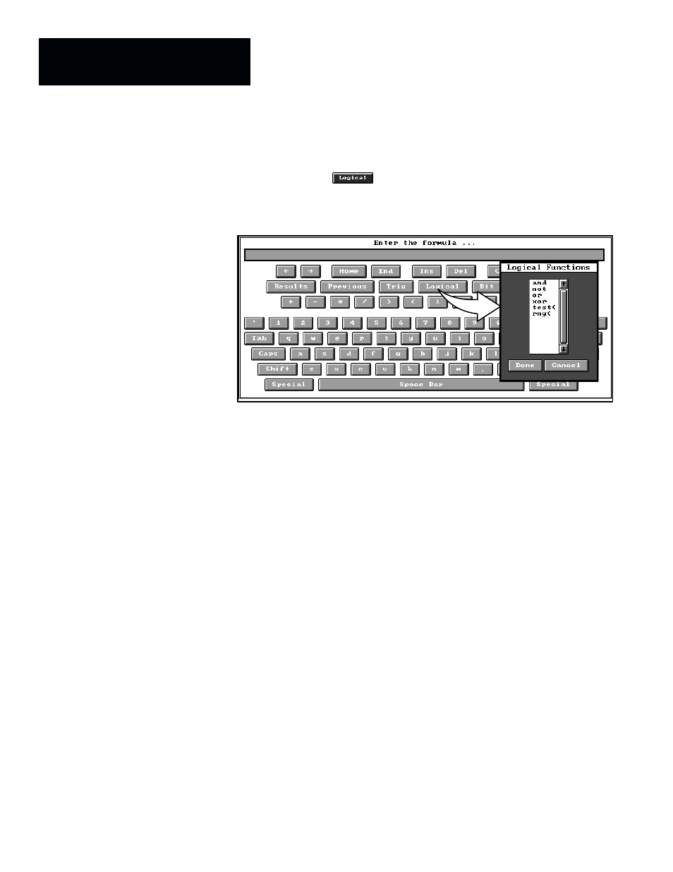
Logical Functions
When you pick the
key, the
Logical Functions
panel appears, as
shown by the example in Figure 7.97.
Figure 7.97 Example: Selecting the Logical Functions Panel
ЗЗЗЗЗ
ЗЗЗЗЗ
ЗЗЗЗЗ
The
Logical Functions
panel lists all of the logic operators that are available
to a math tool.
The “
and
,” “
or
,” and “
xor
” logic operators perform logical operations when
placed between two values in a formula, whereas the “
not
” operator is placed
ahead of an expression containing other logic operators. The “
test
” operator
requires a single value to be placed immediately after the opening
parenthesis (and must be followed by a closing parenthesis). The “
rng
”
operator requires three values.
The value(s) used with a logic operator are usually inspection results of some
kind. They are always either zero or non–zero, and can be thought of as
“inputs” to a logic operator. Thus, if an input value is zero, it is considered to
be “false,” and if it is non–zero, it is considered to be “true.” The result or
“output” from all of these logic operators is either a logic “1” or a logic “0,”
according to whether or not the input logic condition is satisfied for the
particular logic operator.
Here is a brief description of each logic operator and an example of its use:
and –– The “
and
” logic operator is inserted between two or more
expressions (such as inspection results values) in a formula. If the value of
each expression (“input”) is logic “1” (or non–zero), the result of the logic
operation (“output”) will be a logic “1.” If any input is zero, however, the
output of the formula will be a logic “0.”
Figure 7.98 (page 7–125) uses a simple example of a formula to illustrate the
relation of the “
and
” logic operation in a formula.