Rockwell Automation 5370-CVIM2 Module User Manual
Page 52
5
Chapter
Chapter 3
Image Acquisition Parameters
3–13
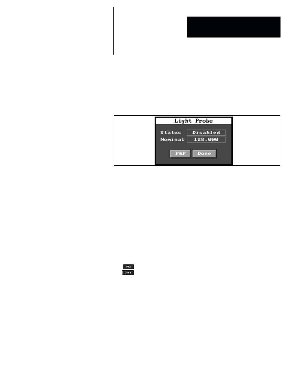
Light Probe Panel
The
Light Probe
panel, shown in Figure 3.8, contains two fields and two
buttons: The
Status
field, which enables or disables the light probe tool, and
the
Nomina
l field performs a “learn” operation, which causes the light probe
tool to acquire a sample or “nominal” luminance reading.
Figure 3.8 Light Probe Panel
Status –– The light probe status is indicated by the
Status
field in the
Light
Probe
panel. By default, the status is
Disabled
.
When you pick the
Status
field, the status toggles from
Disabled
to
Enabled
, or vice versa, with the following effects:
•
Disabled –– This indicates that the light probe for the associated camera
is inactive, and lighting compensation will not be provided.
•
Enabled –– This means that the light probe for the associated camera is
active, and lighting compensation will be provided.
Nominal –– The nominal value is indicated by the
Nominal
field in the
Light
Probe
panel. When you pick the
Nominal
field, the light probe performs a
“learn” operation, during which it calculates the average luminance of the
pixels in the light probe box and displays the result in the
Nominal
field.
The
button enables you to position and “size” the light probe box, and
the
button exits the light probe setup and returns to the
Camera
panel.
Light Probe “Tool Type” and Range Limits
Range limits can be selected for a light probe by selecting a
Probe
tool type
in the toolset edit panel, as shown in Figure 3.9 (page 3–14).
When you pick
Probe
in the toolset edit panel, the
Range
panel appears, as
shown in Figure 3.9. Note that the nominal value (from the “learn” operation
described earlier) appears in the
Range
panel. Using the nominal value as
the basis for determining the appropriate range limits, select the range limits
as described in Chapter 7, Inspection Tools, on page 7–179.