Rockwell Automation 5370-CVIM2 Module User Manual
Page 134
Chapter 5
Pick and Place Function
5–4
The
Pick & Place
panel for the arc gage contains the following data display
fields and buttons:
•
X Cen; Y Cen –– These two fields display, respectively, the current X
and Y coordinates of the center point of the arc.
•
Radius –– This field displays the current arc radius in pixels.
•
Theta –– This field displays the current location, in radians, of the “head”
of the arc, with respect to the 3 o’clock position of the arc. The radian
value increases clockwise from that point.
•
Radians –– This field displays the current arc size in radians.
•
Arrow buttons,
↑, ↓, ←, and → –– When you pick an arrow button, by
default the entire arc moves one pixel in the direction of the
corresponding arrow. If, however, you have just picked and placed the
“head” or “tail” of the arc, the arrow buttons will affect that part of the arc
only.
•
Done –– When you have set the arc’s position and size as required for the
application, pick the
button to exit the pick and place function and
return to the tool edit or adjust panel.
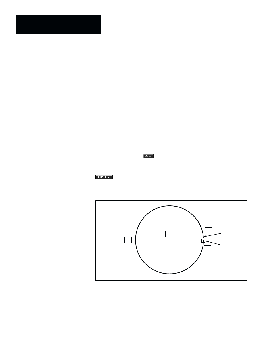
Figure 5.4 shows how an arc appears in its default state after you pick the
button. Note that in this state the arc is nearly a full circle, with the
two ends at the 3 o’clock position nearly touching.
Figure 5.4 Pick and Place Points for an Arc
•
Pick and
place points
B
A
D
C
Head
Tail
As Figure 5.4 shows, pick and place points are located at the arc center (A),
the “head” and “tail” (B and C), and the midpoint (D) between (B and C).
The function of point (A) depends on which of the two pick and place modes
you select: fixed center, or fixed ends. When you select the fixed center
mode, the center (indicated by the
•
) remains anchored in the image field;
whereas, when you select the fixed ends mode, the two ends of the arc remain
anchored in the image field.