X’, x then y – Rockwell Automation 5370-CVIM2 Module User Manual
Page 167
Chapter 6
Reference Tools
6–8
X’, X then Y
The X’, X then Y reference line operation consists of three reference lines,
two that lie along the horizontal (X) axis of the image field, and one that lies
along the vertical (Y) axis. This operation is appropriate in applications
where workpiece shift and rotation are expected.
In operation, the X’, X then Y reference line operation evaluates the two
X–axes first for X–axis shift and for rotation, using the difference in the
amount of shift along both X–axes to calculate the number of degrees of
rotation. It applies X–axis shift compensation to the Y–axis, as required,
before evaluating the Y–axis for workpiece shift. (Note that the Y–axis is not
rotated prior to analysis.)
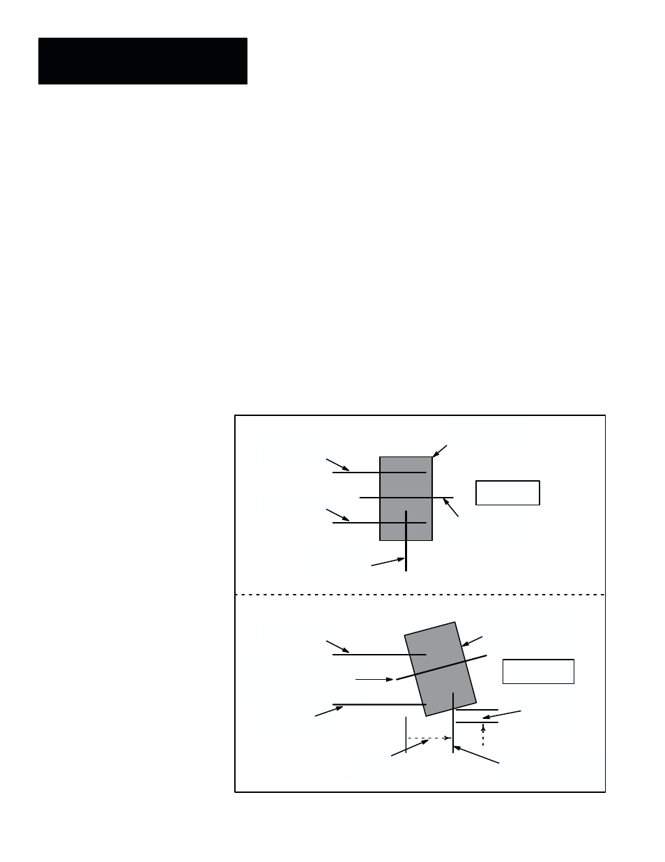
Figure 6.7 illustrates the three X’, X then Y reference lines detecting a
shifted and rotated workpiece, applying the X–axis shift to the Y–axis, then
detecting Y–axis shift in the same workpiece and applying the combined
X–Y shift and rotation to the associated line gage.
Figure 6.7 Example: Using the X’, X Then Y Reference Line Operation
Y–axis with X–axis shift
compensation applied
Workpiece:
nominal position
X–axis
reference line
X–axis
workpiece
shift
Line gage:
original position
X–axis
reference line
Y–axis
reference line
X–axis
reference line
X–axis
reference line
Workpiece:
position after shift
and rotation
Y–axis
workpiece
shift
Line gage: with X– and
Y–axis shift and rotation
compensation applied
INSPECTED
POSITION
NOMINAL
POSITION