Trigger setup panel – Rockwell Automation 5370-CVIM2 Module User Manual
Page 83
Chapter 3
Image Acquisition Parameters
3–44
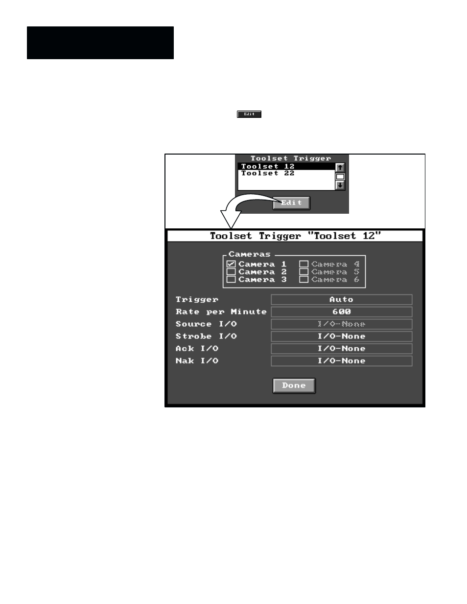
When you highlight a toolset trigger name in the
Toolset Trigger
scrolling
list and then pick the
button below the list, the corresponding
Toolset Trigger
setup panel appears, as shown in Figure 3.31.
Figure 3.31 Example: Selecting Trigger Setup Panel
ЗЗЗЗЗЗЗ
ЗЗЗЗЗЗЗ
ЗЗЗЗЗЗЗ
ЗЗЗЗЗЗЗ
NOTE: Initially, the term “
None
” appears in this list. A toolset trigger
name will appear in the
Toolset Trigger
list only after an inspection name
has been defined for a toolset in the Configuration Editor panel, as described
in Chapter 4, Inspection Configuration, on page 4–9.
The selections in the
Toolset Trigger
setup panel determine the camera port,
the trigger source, and four of the discrete I/O settings for online inspection
operations. These selections apply only to the particular toolset named in the
title bar of the
Toolset Trigger
panel. Thus, in the example in Figure 3.31,
the toolset is named “
Toolset 12.
”
Here is a brief description of the selections in the
Toolset Trigger
panel:
•
Cameras –– This selects the camera(s) to be used for the toolset.
•
Trigger –– This selects the trigger source for the toolset.
•
Rate per Minute –– When “
Auto
” is selected as the (internal) trigger
source, this selects the number of trigger signals per minute.
Trigger Setup Panel