Rockwell Automation 5370-CVIM2 Module User Manual
Page 443
Chapter 8
Thresholds, Filters, and Morphology
8–4
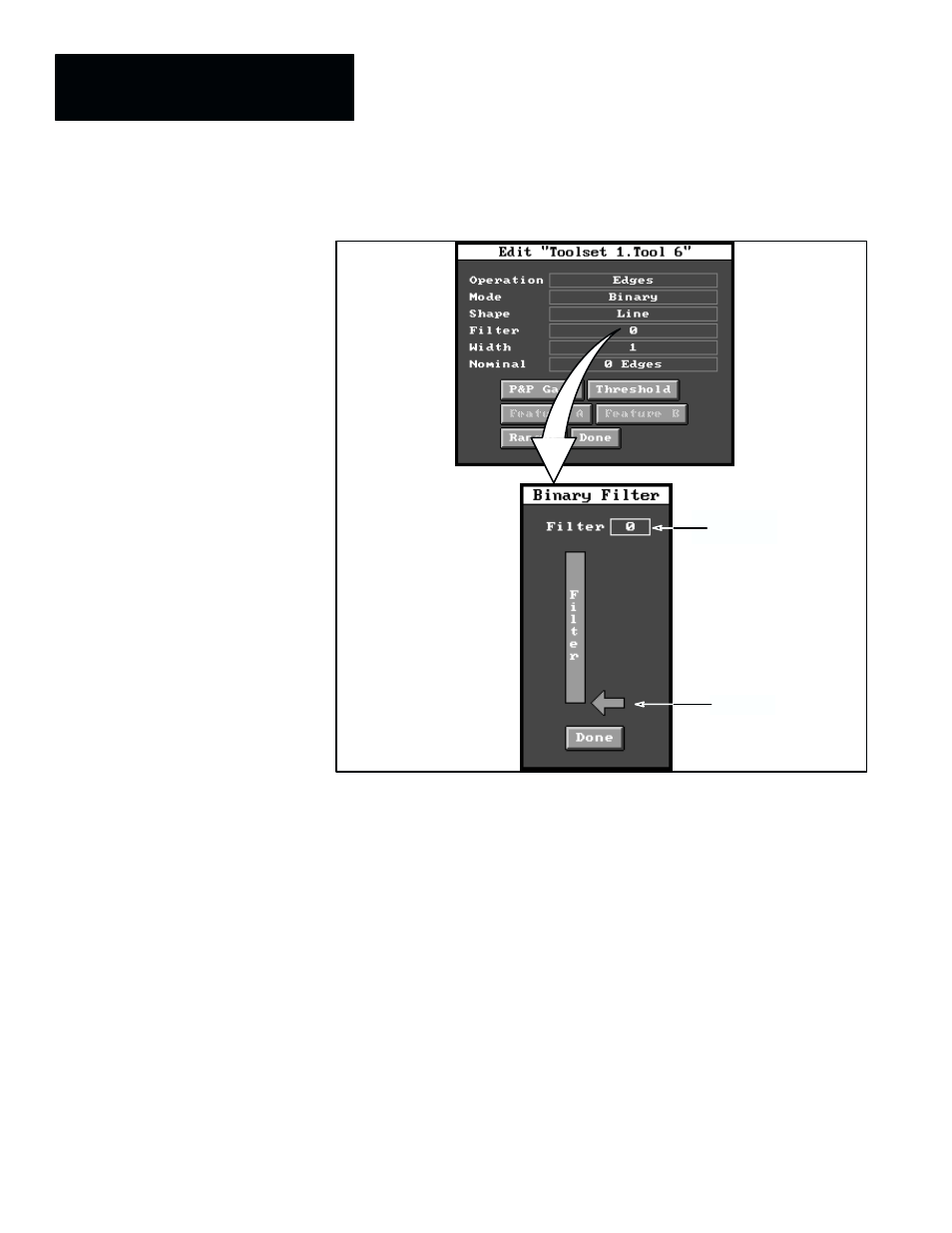
Figure 8.3 Selecting Binary Filter Panel for Gage
Cursor
Filter value
field
ЙЙЙЙ
ЙЙЙЙ
ЙЙЙЙ
ЙЙЙЙ
ЙЙЙЙ
ЙЙЙЙ
ЙЙЙ
ЙЙЙ
ЙЙЙ
From the
Binary Filter
panel you can select the number (from 0 to 10) of
consecutive black or white noise pixels to be masked (filtered) from the
workpiece image and background, in the area around the gage, before the
gage looks for edges. The default filter value is 0, as shown in Figure 8.3.
Thus, the effect of the filtering function is to mask out the noise so that it
does not create false or unwanted edges on the gage. (The noise will remain
visible in the binary box, however.)
This is how the filter function works: If the filter value were set to 3, for
example, and the gage encountered three (or fewer) consecutive white pixels
in a stream of black pixels, these white pixels would be regarded as noise and
“filtered” out; thus, the gage would not detect any edges at that point.
Conversely, if the gage encountered a group of four (or more) consecutive
white pixels, the gage would detect two edges –– a leading edge and a
trailing edge.
To use the filter function, you can pick the cursor and drag it upward to
increase the filtering value; or, you can pick the filter value field and select a
new filter value using the calculator pad. The objective is to set the filter to a