Reference window tool configuration – Rockwell Automation 5370-CVIM2 Module User Manual
Page 188
5
Chapter
Chapter 6
Reference Tools
6–29
2. Save feature image:
a.
“Pick and place” –– position the feature window over the
appropriate feature on the workpiece image.
b. Select feature image compression parameters
c.
Specify file name –– use the Image Manager to enter a device code
and feature name, then store the feature image in a file on the
selected device.
3. Configure search window:
a.
“Pick and place” –– position the search window over the
appropriate part of the workpiece image.
b. Select number of passes –– select the number of passes (one or
two) that the feature window will make through the search
window.
c.
Select “pass” parameters –– select the appropriate masking,
scaling, and other parameters for each “pass.”
4. Repeat Steps 1 – 3 for a second feature, if required.
5. Learn nominal values –– perform a “learn” operation to “learn” and
store the “nominal” values –– the data that indicate the workpiece’s
initial position.
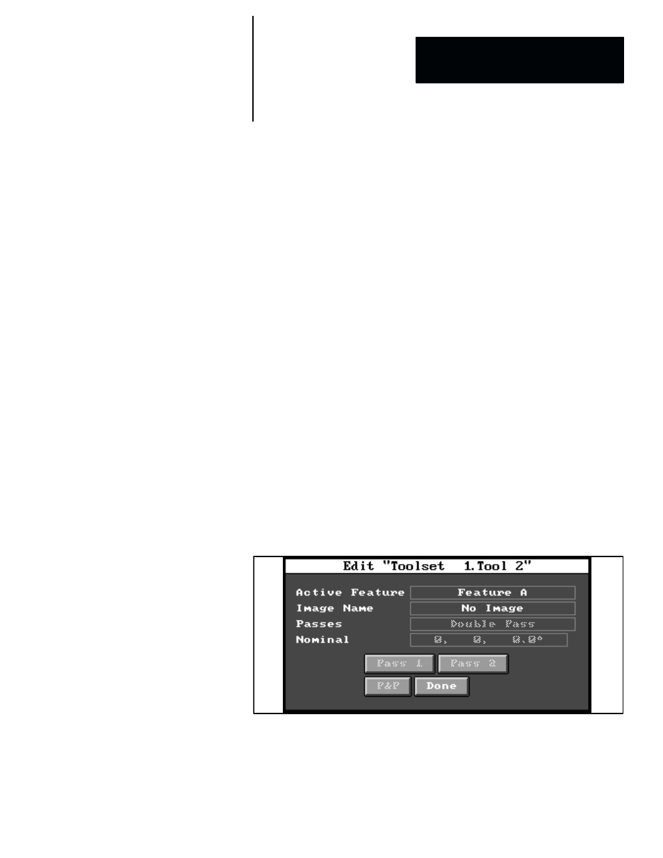
This section discusses the configuration steps that are accessed from the
fields and buttons in the example reference window tool edit panel shown in
Figure 6.24. Note that most of these fields and buttons are inactive (shaded)
until the appropriate points are reached in the configuration process.
Figure 6.24 Example: Reference Window Tool Edit Panel
Reference Window Tool
Configuration