Rockwell Automation 5370-CVIM2 Module User Manual
Page 451
Chapter 8
Thresholds, Filters, and Morphology
8–12
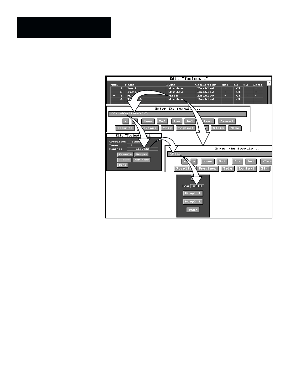
Figure 8.9 Example: Using the Dynamic Threshold Function
ЙЙЙЙ
ЙЙЙЙ
ЙЙЙЙ
ЙЙЙЙ
ЙЙЙ
ЙЙЙ
ЗЗЗЗЗЗЗ
ЗЗЗЗЗЗЗ
ЗЗЗЗЗЗЗ
ЗЗЗЗЗЗЗ
ЗЗЗЗЗЗЗ
ЗЗЗЗЗ
ЗЗЗЗЗ
ЗЗЗЗЗ
ЙЙЙЙ
ЙЙЙЙ
ЙЙЙЙ
ЙЙЙЙ
ЙЙЙЙ
ЙЙ
ЙЙ
ЙЙ
ЙЙЙ
ЙЙЙ
ЙЙЙ
ЙЙЙ
ЙЙ
ЙЙ
In this example, the toolset contains, in order, the following tools: two
window tools, a math tool, and another window tool. The first two windows
are configured for luminance operations; one acquires the background
luminance value of the image field, while the other acquires the foreground
luminance value.
The math tool formula is configured to average the two luminance values,
and the third window, configured to count pixels, uses the math tool result in
its “
Low
” threshold setting to dynamically alter the low threshold value when
the light level changes. The math tool formula uses the window tools’ names
to represent the luminance values from them, and, as shown in Figure 8.9, it
takes the following form:
({back}+{fore})/2
Since the math tool’s name is “
mid
,” the math formula for the third window’s
“
Low
” threshold can use that name to acquire the results from the math tool.
In the Figure 8.9 example, the current average value from the math tool’s
calculation is “
113.922
” (see the “
Nominal
” field in the math tool’s edit
panel). The third window, using “
{mid}
” in the “
Low
” threshold’s math
formula, acquires the math tool result, and that value (rounded off) appears
as “
=113
” in the “
Low
” threshold box. During run operations, this value will
vary according to changes in the external light levels, and it will thereby
maintain the correct “
Low
” threshold setting for the window.