Vertical reference source – Rockwell Automation 5370-CVIM2 Module User Manual
Page 67
Chapter 3
Image Acquisition Parameters
3–28
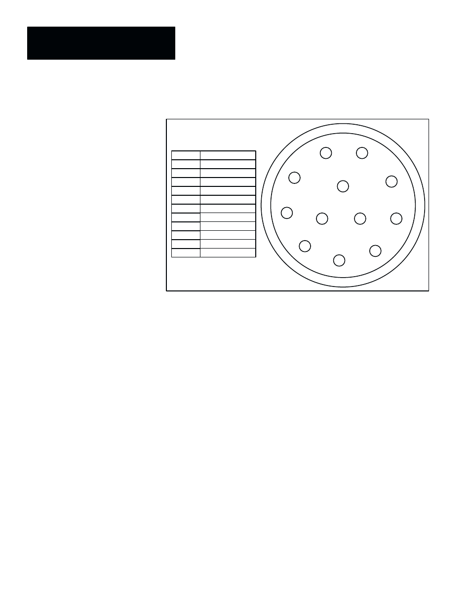
Figure 3.20 Pinout Diagram: CVIM2 Front Panel Camera Connector
+12V Out
Gnd
Video In (G)
Ext HD Out (G)
Video In
Ext HD Out
Gnd
Gnd
NC
+12V Out
Ext VD Out (G)
Pin 2
Pin 3
Pin 4
Pin 5
Pin 6
Pin 7
Pin 8
Pin 9
Pin 10
Pin 11
Pin 1
1
2
3
4
5
6
7
8
9
10
11
12
View: Facing a camera connector
on the CVIM2 front panel
Ext VD Out
Pin 12
Vertical Reference Source
For most applications, the CVIM2 system can supply vertical timing or
“sync” signals for all cameras. However, for some applications (except those
using frame reset cameras) an external vertical timing source, synchronous
or asynchronous, may be required. Here are three application situations using
an external vertical reference:
•
A non–standard camera is used, and it generates its own vertical (and
horizontal) timing signals and cannot be driven from the CVIM2 system.
•
A “genlock” timing device is used to synchronize all CVIM2 systems and
cameras when multiple systems and/or cameras are used.
•
Two CVIM2 systems are used, and camera #1 on one system (the master)
supplies vertical (but not horizontal) “sync”to camera #1 on the other
system (the slave) through the camera #4 connector on each system.
Cameras #2 and #3 on the two systems can be linked in a similar manner
through the camera #5 and #6 connectors on each system.
In the first two situations, where both the vertical and the horizontal timing
signals must be synchronized externally “
External, Synchronous, Cam.4
In
” must be selected in the
Vertical Reset Source
box. In the third
situation, where only the vertical timing signals are synchronized, “
External,
Asynchronous, Cams.4, 5 and 6 In
” must be selected.