Rockwell Automation 5370-CVIM2 Module User Manual
Page 278
Chapter 7
Inspection Tools
7–40
areas of objects 2 through 9 lie between these two values. Thus, the window
measures the largest ten objects.
In example (C), the “
)” symbol appears on the “
Height
” line. The numbers
1 through 10 identify the objects on the basis of their height –– in ascending
order –– from the shortest to the tallest. In this example, the shortest object
(1) is 34 pixels in height, and the tallest object (10) is 38 pixels in height.
The heights of objects 2 through 9 lie between these two values. Thus, the
window measures the shortest ten objects.
NOTE: The status of a measurement function (
Y
= active;
N
= inactive) has
no effect on the sorting function. Also, the maximum possible number of
numbered objects (when all contours are recognized as objects) can be
limited by the current
Max Results
setting. Thus, in the examples above, all
15 contours are recognized as objects, but since the
Max Results
setting is
10, only the first ten are numbered and measured.
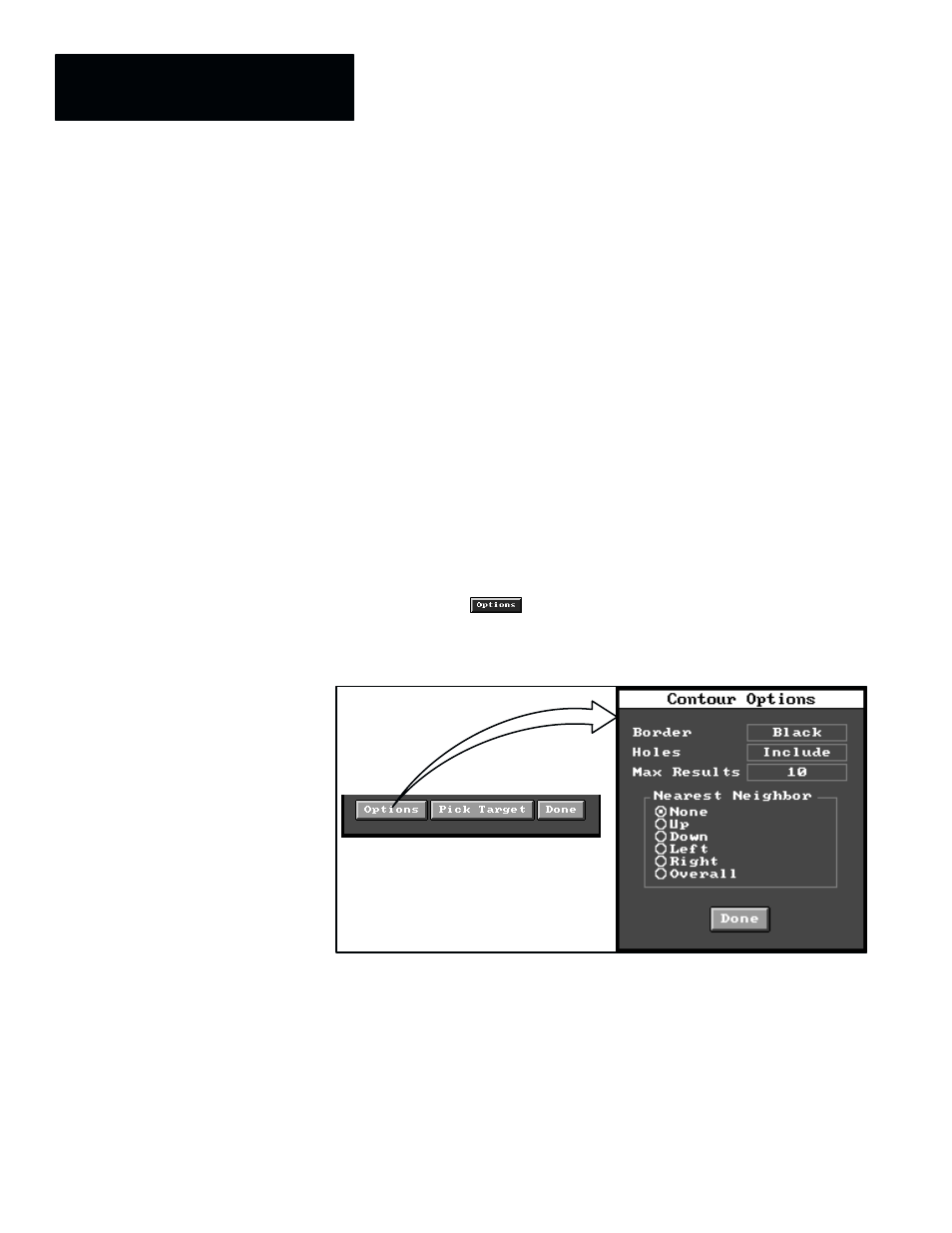
Contour Options Panel
When you pick the
button in the
Target
panel, the
Contour Options
selection panel appears, as shown by Figure 7.35.
Figure 7.35 Selecting Contour Options Panel
ЙЙЙЙЙЙЙЙЙЙ
ЙЙЙЙЙЙЙЙЙЙ
ЙЙЙЙЙЙЙЙЙЙ
ЙЙЙЙЙЙЙЙЙЙ
ЙЙЙЙЙЙЙЙЙЙ
Here is a brief description of the fields and button in the
Contour Options
selection panel.
•
Border –– This field selects either a white border or a black border for
the window, with the following consequences:
— If the border color selection is
Black
, any black group of pixels that
touches the border is not a contour.
— If the border color selection is
White
, any white group of pixels that
touches the border is not a contour.