Rockwell Automation 5370-CVIM2 Module User Manual
Page 318
Chapter 7
Inspection Tools
7–80
Image Subtraction: S1 – S2, S1 – S1’, S1 – T
In an image subtraction operation, the image tool subtracts an AOI in the
secondary image designated by
S2
or
S1’
(or a “template” designated as T)
from an AOI in the primary image designated by
S1
, and places the resulting
image in the designated destination buffer. More specifically, the value of
each pixel in the
S2
,
S1’
, or
T
image is subtracted from the value of each
corresponding pixel in the
S1
image. This results in a signed image; that is,
an image whose pixel values lie between –128 and 127.
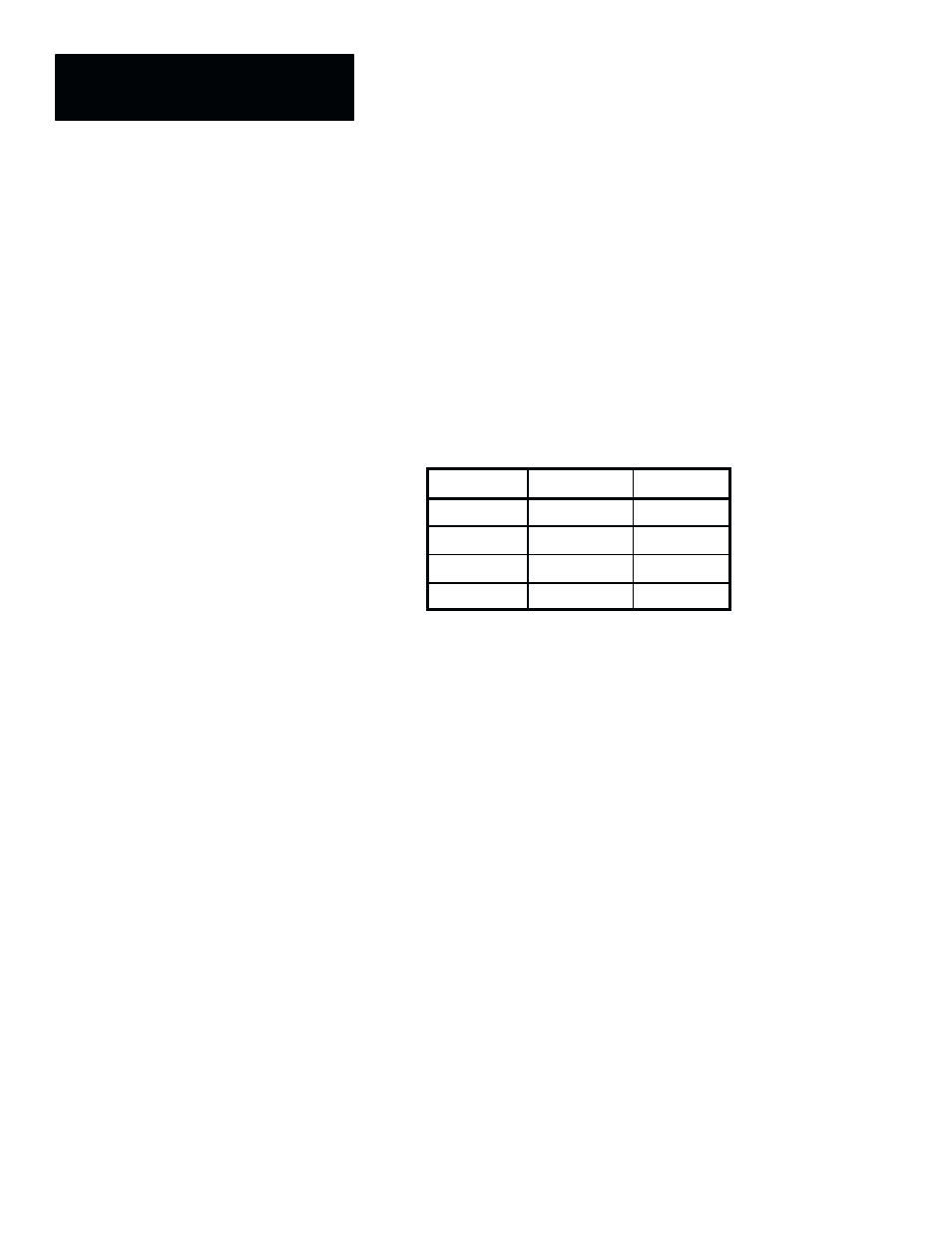
If S1 and S2 (or S
Ȁ or T) are binary images, a logic XOR (“exclusive OR”)
function will be performed on the two images, as shown by the following
table:
S1
S2, S
Ȁ, or T
Pn or Bn
Black
Black
Black
Black
White
White
White
Black
White
White
White
Black
NOTE: Since image subtraction creates a signed image, the “
Sign
,”
“
Absolute
,” “
S.Threshold
” or “
S.Clip
” LUT should be used in order to
remove negative values from the image. The
Sign
,
S.Threshold
, and
S.Clip
LUTs add 128 to each pixel value, thereby placing all values in the 0 to 255
range that the inspection tools require to identify and evaluate features
properly. The
Absolute
LUT changes all negative values to positive values.
Typically, image subtraction is used to cancel all features that are common to
two images and leave only those features that are different between the two
images.
The similarities and differences between the image subtraction operations are
detailed in the following sections.
S1 – S2
The
S1 – S2
image arithmetic operation subtracts an AOI within the
S2
image from an AOI within the
S1
image.
Figure 7.65 (page 7–81) is an example of how an
S1 – S2
operation could
be set up in the toolset edit panel.