Rockwell Automation 5370-CVIM2 Module User Manual
Page 109
5
Chapter
Chapter 4
Inspection Configuration
4–23
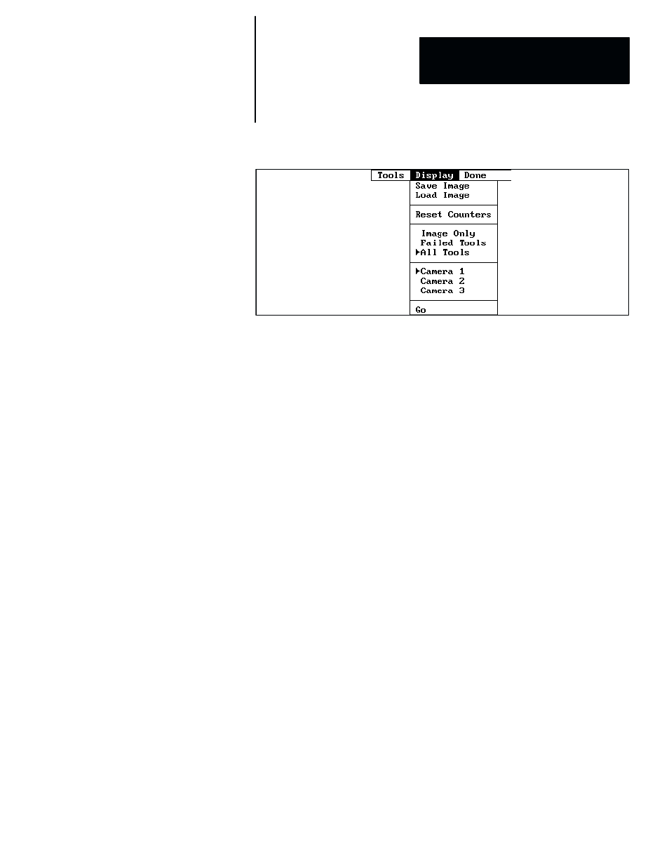
Figure 4.16 Display Menu Example
The
Display
menu determines the appearance of the setup mode
image/tool display panel during tool evaluation. The five sections in this
menu have these meanings:
•
The top section enables you to save an image in compressed form, and
reload the image later.
•
The second section enables you to reset counters and statistics in the
results panels and the results detail panels.
•
The third section determines what will appear in the display panel
during tool evaluation operations: all enabled inspection tools, the
failed tools only, or the camera image only.
•
The fourth section appears only when two or three camera inputs have
been assigned to the current toolset’s trigger.
•
The bottom section enables you to start (and stop) the tool evaluation
operations.
Note that a cursor (➤) points to
All Tools
, while another cursor points to
Camera 1
. These are the current default settings for the display mode
and camera selections.
5. Pick
Go
. When you do, the image/tool display panel is enabled, with
these results:
•
If the
Auto
trigger source is selected, a continuous series of camera
images will appear on the screen immediately, such as is shown in
Figure 4.17 (page 4–24).
•
If an external trigger source is selected, the system must receive a
trigger signal in order to display a camera image.
•
If inspection tools had been previously configured (and
All Tools
selected), those tools would also appear at this time.