Rockwell Automation 5370-CVIM2 Module User Manual
Page 286
Chapter 7
Inspection Tools
7–48
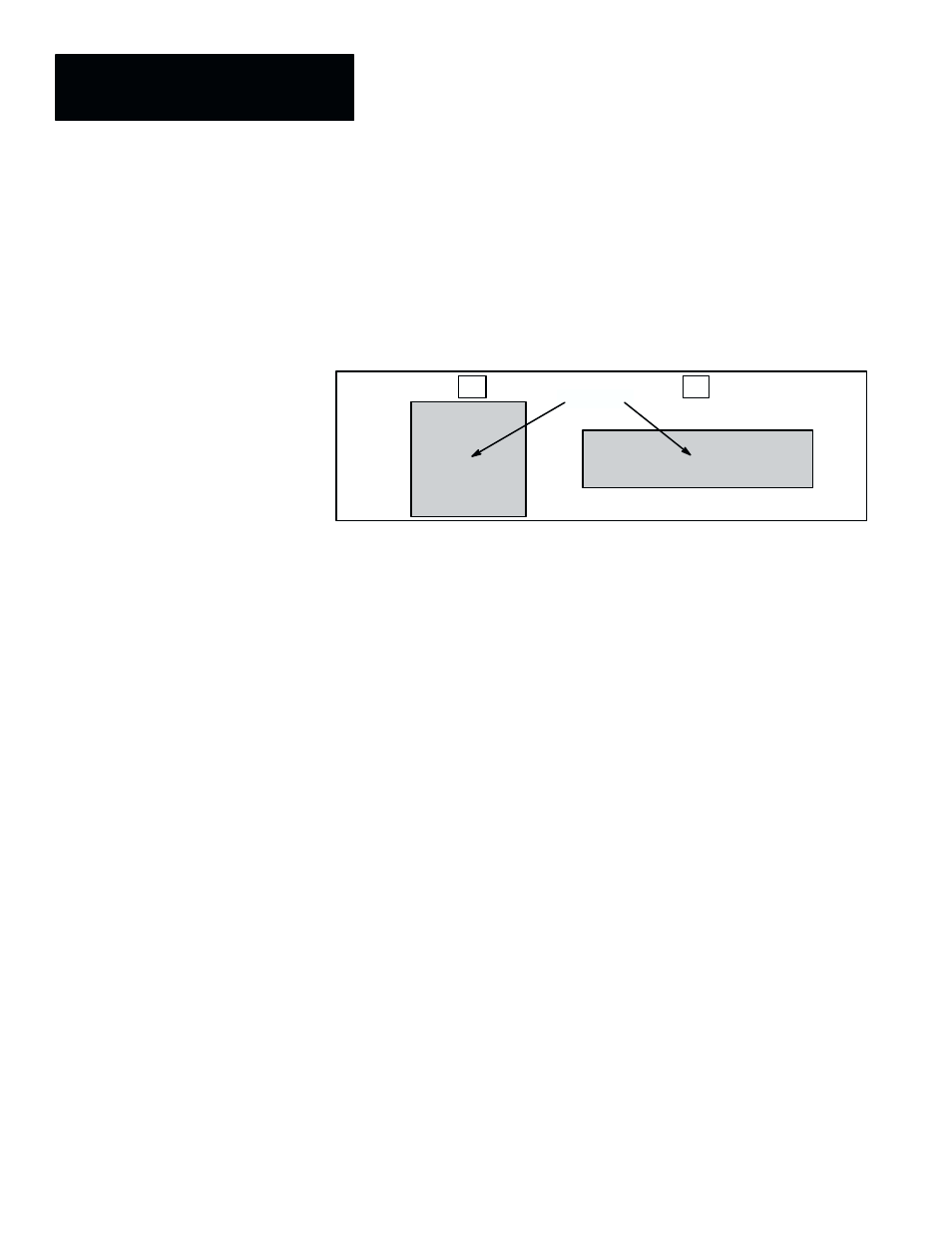
Inertia –– The sum, over all pixels within the contour, of the squared
distance from the centroid to each pixel. This is equivalent to the moment of
inertia of the contour if rotated about its centroid. A contour with its mass
distributed close to its centroid, such as (A) in Figure 7.42, has less inertia
than a contour of the same area with its mass widely distributed, such as (B)
in Figure 7.42.
Figure 7.42 Example: Inertia of Two Objects With Identical Areas
+
+
A
B
Centroid
Theta –– Theta measures the angle between the major axis of an object and
the X–axis of the image field (assuming 0
° at the 3 o’clock position). Since a
clearly definable major axis is required for this measurement function to
work properly, it cannot be used with circular objects.
Figure 7.43 (page 7–49) illustrates the theta angle of two identical elliptical
objects with different orientations in the image field. In this example, the
major axis of object (A) is –37.8
° (counterclockwise) from the X–axis, while
object (B) is 40.2
° (clockwise) from the X–axis.
Note that the maximum measurable angle in each direction is 90.0
°
(clockwise) and –90.0
° (counterclockwise), since there is no provision for
resolving the direction of the major axis. For example, if the object in
Figure 7.43 (A) were to rotate counterclockwise past the –90.0
° point, its
theta would become positive.
NOTE: Although the angle values appear in the
Pick Target
panel with an
apparent accuracy of one place to the right of the decimal, the actual values
available to the math tool are stored with the full floating point accuracy.