Physical layer architecture, Figure 4–9. physical layer – Altera IP Compiler for PCI Express User Manual
Page 73
Chapter 4: IP Core Architecture
4–15
Physical Layer
August 2014
Altera Corporation
IP Compiler for PCI Express User Guide
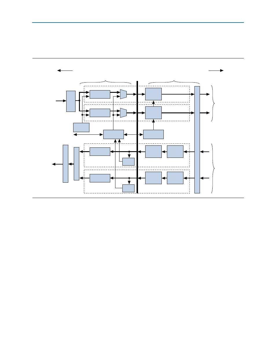
Physical Layer Architecture
illustrates the physical layer architecture.
The physical layer is subdivided by the PIPE Interface Specification into two layers
(bracketed horizontally in
■
Media Access Controller (MAC) Layer—The MAC layer includes the Link
Training and Status state machine (LTSSM) and the scrambling/descrambling and
multilane deskew functions.
■
PHY Layer—The PHY layer includes the 8B/10B encode/decode functions, elastic
buffering, and serialization/deserialization functions.
The physical layer integrates both digital and analog elements. Intel designed the
PIPE interface to separate the MAC from the PHY. The IP core is compliant with the
PIPE interface, allowing integration with other PIPE-compliant external PHY devices.
Depending on the parameters you set in the parameter editor, the IP core can
automatically instantiate a complete PHY layer when targeting an Arria II GX, Arria
II GZ, Cyclone IV GX, HardCopy IV GX, Stratix II GX, or Stratix IV GX device.
Figure 4–9. Physical Layer
Scrambler
8B10B
Encoder
Lane n
Tx+ / Tx-
Scrambler
8B10B
Encoder
Lane 0
Tx+ / Tx-
Descrambler
8B10B
Decoder
Lane n
Rx+ / Rx-
Elastic
Buffer
LTSSM
State Machine
SKIP
Generation
Control & Status
PIPE
Emulation Logic
Link Ser
ializ
er
for an x8 Link
Tx Packets
Rx MAC
Lane
De
v
ice
T
ranscei
v
er (per Lane)
w
ith 2.5 or 5.0 G
b
ps SERDES & PLL
Descrambler
8B10B
Decoder
Lane 0
Rx+ / Rx-
Elastic
Buffer
Rx MAC
Lane
PIPE
Interface
M
u
ltilane Desk
e
w
Link Ser
ializ
er f
or an x8 Link
Rx Packets
Transmit
Data Path
Receive
Data Path
MAC Layer
PHY layer
To Link
To Data Link Layer