Pci express interrupts for root ports, Figure 10–5, Figure 10–6 – Altera IP Compiler for PCI Express User Manual
Page 194
10–4
Chapter 10: Interrupts
PCI Express Interrupts for Root Ports
IP Compiler for PCI Express User Guide
August 2014
Altera Corporation
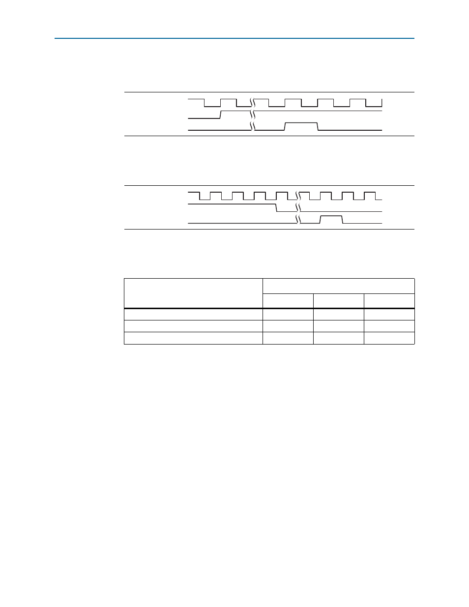
illustrates interrupt timing for the legacy interface. In this figure the
assertion of app_int_ack indicates that the Assert_INTA message TLP has been sent.
illustrates the timing for deassertion of legacy interrupts. The assertion of
app_int_ack
indicates that the Deassert_INTA message TLP has been sent.
describes 3 example implementations; 1 in which all 32 MSI messages are
allocated and 2 in which only 4 are allocated.
MSI interrupts generated for hot plug, power management events, and system errors
always use TC0. MSI interrupts generated by the application layer can use any traffic
class. For example, a DMA that generates an MSI at the end of a transmission can use
the same traffic control as was used to transfer data.
PCI Express Interrupts for Root Ports
In root port mode, the PCI Express IP core receives interrupts through two different
mechanisms:
■
MSI—Root ports receive MSI interrupts through the Avalon-ST RX TLP of type
MWr
. This is a memory mapped mechanism.
■
Legacy—Legacy interrupts are translated into TLPs of type Message Interrupt
which is sent to the application layer using the int_status[3:0] pins.
Normally, the root port services rather than sends interrupts; however, in two
circumstances the root port can send an interrupt to itself to record error conditions:
Figure 10–5. Legacy Interrupt Assertion
Figure 10–6. Legacy Interrupt Deassertion
Table 10–1. MSI Messages Requested, Allocated, and Mapped
MSI
Allocated
32
4
4
System error
31
3
3
Hot plug and power management event
30
2
3
Application
29:0
1:0
2:0
clk
app_int_sts
app_int_ack
clk
app_int_sts
app_int_ack