Lmi signals—hard ip implementation, Fer to the, Lmi signals—hard ip implementation” on – Altera IP Compiler for PCI Express User Manual
Page 123
Chapter 5: IP Core Interfaces
5–37
Avalon-ST Interface
August 2014
Altera Corporation
IP Compiler for PCI Express User Guide
LMI Signals—Hard IP Implementation
LMI writes log error descriptor information in the AER header log registers. These
writes record completion errors as described in
“Completion Signals for the Avalon-
.
Altera does not recommend using the LMI bus to access other configuration space
registers for the following reasons:
■
LMI write—An LMI write updates the internally captured bus and device
numbers incorrectly; however, configuration writes received from the PCIe link
provide the correct bus and device numbers.
■
LMI read—For other configuration space registers, an LMI request can fail to be
acknowledged if it occurs at the same time that a configuration request is
processed from the RX Buffer. Simultaneous requests may lead to collisions that
corrupt the data stored in the configuration space registers.
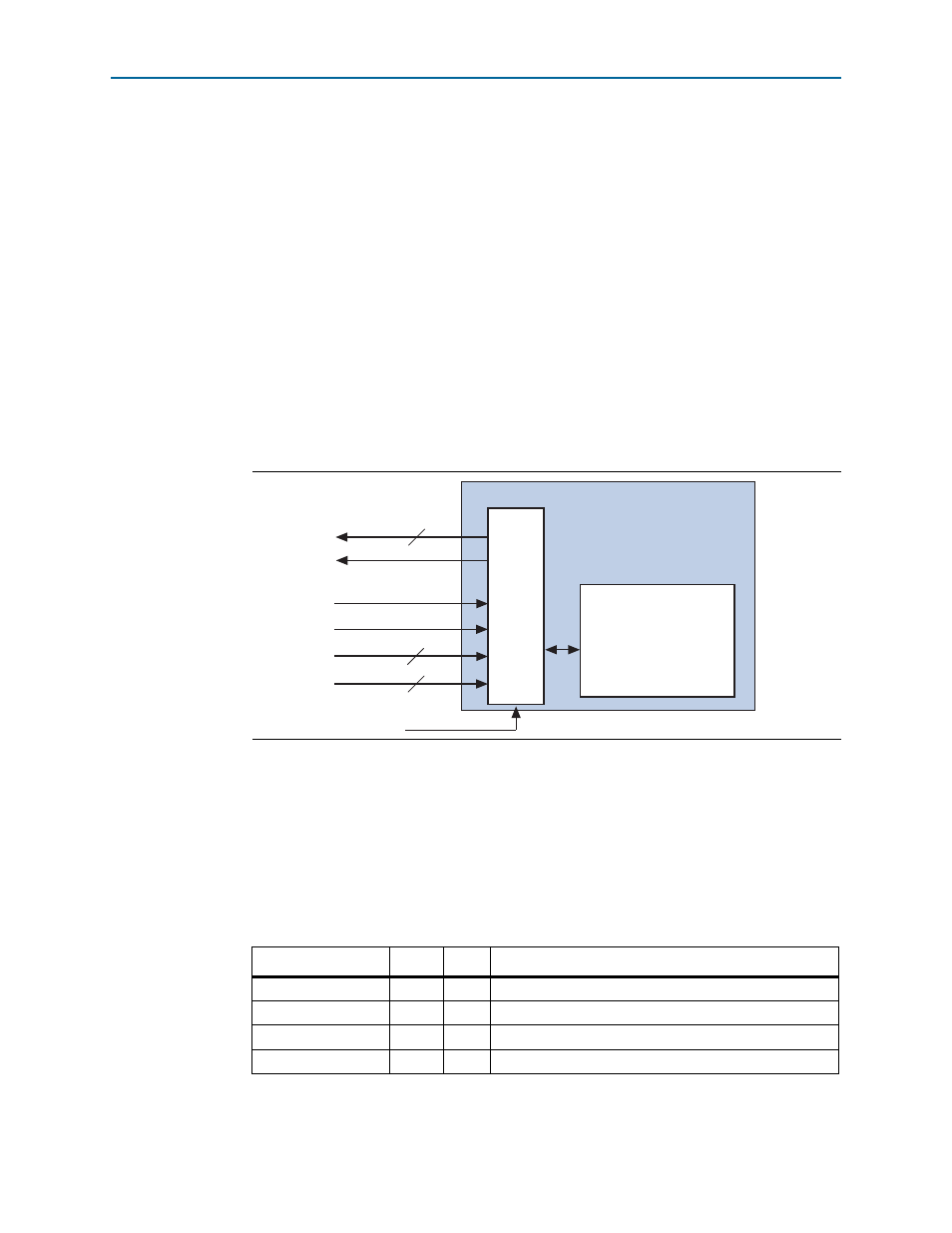
illustrates the LMI interface.
The LMI interface is synchronized to pld_clk and runs at frequencies up to 250 MHz.
The LMI address is the same as the PCIe configuration space address. The read and
write data are always 32 bits. The LMI interface provides the same access to
configuration space registers as configuration TLP requests. Register bits have the
same attributes, (read only, read/write, and so on) for accesses from the LMI interface
and from configuration TLP requests.
describes the signals that comprise the LMI interface.
Figure 5–32. Local Management Interface
Table 5–17. LMI Interface
Signal
Width
Dir
Description
lmi_dout
32
O
Data outputs
lmi_rden
1
I
Read enable input
lmi_wren
1
I
Write enable input
lmi_ack
1
O
Write execution done/read data valid
Configuration Space
128 32-bit registers
(4 KBytes)
LMI
32
lmi_dout
lmi_ack
12
lmi_addr
32
lmi_din
lmi_rden
lmi_wren
pld_clk
IP Compiler for
PCI Express