Clock signals—hard ip implementation, Clock signals—soft ip implementation – Altera IP Compiler for PCI Express User Manual
Page 109
Chapter 5: IP Core Interfaces
5–23
Avalon-ST Interface
August 2014
Altera Corporation
IP Compiler for PCI Express User Guide
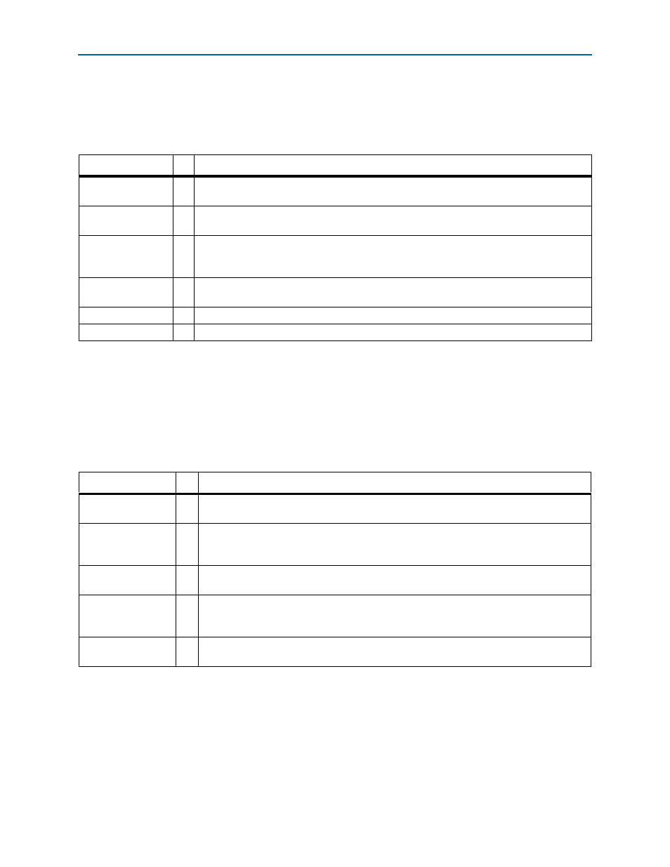
Clock Signals—Hard IP Implementation
describes the clock signals that comprise the clock interface used in the hard
IP implementation.
Refer to
for a complete description of the clock interface
for each IP Compiler for PCI Express variation.
Clock Signals—Soft IP Implementation
Table 5–5. Clock Signals Hard IP Implementation
Signal
I/O
Description
refclk
I
Reference clock for the IP core. It must be the frequency specified on the System Settings page
accessible from the Parameter Settings tab using the parameter editor.
pld_clk
I
Clocks the application layer and part of the adapter. You must drive this clock from
core_clk_out
.
core_clk_out
O
This is a fixed frequency clock used by the data link and transaction layers. To meet PCI Express
link bandwidth constraints, it has minimum frequency requirements which are outlined in
pclk_in
I
This is used for simulation only, and is derived from the refclk. It is the PIPE interface clock
used for PIPE mode simulation.
clk250_out
O
This is used for simulation only. The testbench uses this to generate pclk_in.
clk500_out
O
This is used for simulation only. The testbench uses this to generate pclk_in.
Note to
(1) These clock signals are illustrated by
.
Table 5–6. Clock Signals Soft IP Implementation
Signal
I/O
Description
refclk
I
Reference clock for the IP core. It must be the frequency specified on the System Settings
page accessible from the Parameter Settings tab using the parameter editor.
clk125_in
I
Input clock for the ×1 and ×4 IP core. All of the IP core I/O signals (except refclk,
clk125_out
, and npor) are synchronous to this clock signal. This signal must be connected
to the clk125_out signal. This signal is not on the ×8 IP core.
clk125_out
O
Output clock for the ×1 and ×4 IP core. 125-MHz clock output derived from the refclk input.
This signal is not on the ×8 IP core.
clk250_in
I
Input clock for the ×8 IP core. All of the IP core I/O signals (except refclk, clk250_out, and
npor
) are synchronous to this clock signal. This signal must be connected to the clk250_out
signal.
clk250_out
O
Output from the ×8 IP core. 250 MHz clock output derived from the refclk input. This signal
is only on the ×8 IP core.
Note to
(1) Refer to