True strain control – MTS Series 793 User Manual
Page 371
•
DL = change in specimen gage length
•
L0 = initial gage length
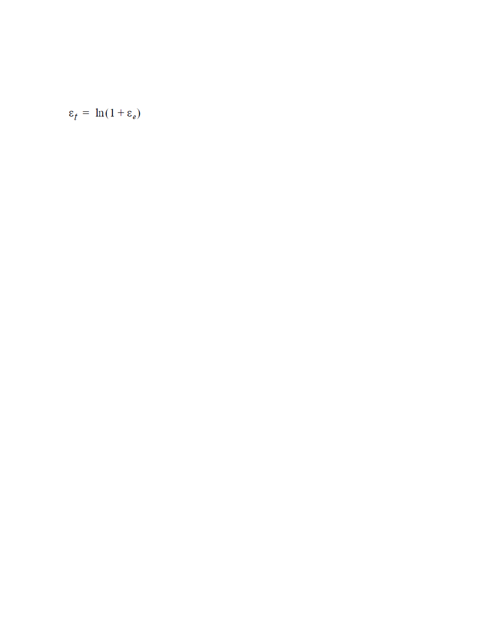
True strain (εt) is the instantaneous change in specimen gage length (DL) divided by instantaneous gage
length (L) as shown in the following equation:
Use the Station Manager’s Calculation Editor to edit the calculation equations for both the strain and true
strain calculated input signals.
True Strain Control
1. Use the Station Builder application to configure the system to include calculated true strain and strain
control modes.
a) In the Station Builder navigation pane, select Channels.
b) On the Control Modes tab, select the <
list, and then click +.
c) In the Internal Name and Display Name boxes, type signal name (True Strain or Strain).
d) Set the Dimension (Strain) and Display Units (in/in or cm/cm) for the calculated input signal.
e) Repeat the above steps to create a calculated input signal for strain.
2. Use the Station Manager application to edit the equations for the strain and true strain calculated input
signals.
a) Open Station Manager, then set the user access level to Configuration.
b) From the Tools menu, select Calculation Editor.
c) Click Calculated Analog Inputs on the navigation pane.
d) Click the strain signal (Axial Strain).
e) Edit the Axial Strain equation by inserting Axial COD/Gage Length (to right of the = sign).
MTS Series 793 Control Software 371
Calculated Signals